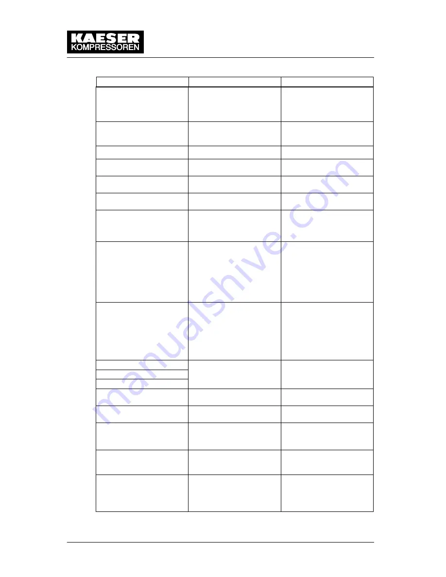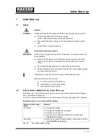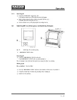
Event Recognition and Fault Rectification
9 --- 48
Message
Remedy
Possible cause
blowoff prot.
Warning
The blowoff pressure of the
pressure relief valve will
soon be reached.
Change the oil separator
cartridge.
Open the shut–off valve in
the venting line.
blt.coup.insp.h
The maintenance interval
for V–belt tension / coupling
inspection has expired.
Visually inspect and tension
the V–belts.
blt.coup.chng. h
V–belts / coupling worn.
Change belts / coupling.
Buffer battery
Battery for retention of data
is discharged.
Replace the battery
bus alarm
Bus link via Profibus DP in-
terface interrupted
Check bus highway and
plug.
Condensate drain
Fault in condensate drain-
age.
Check condensate drain
and lines.
elect. equip. h
The service interval for
checking electrical equip-
ment and installation has
expired.
Reset the service interval
counter.
error: RS 485
Wrong configuration or
transmission error.
Check the link/interface
connections between the
two controllers.
Check maximum cable
length and screening.
1 master and 1 slave confi-
gured.
ext.load signal?
Dubious external load sig-
nal
Increased cut–out pressure
exceeded.
The external load control
has not switched to idle (off
load).
Check settings of the exter-
nal controller.
Take the pressure drops
across filters and dryer into
account.
ext. message 0
Customer specific:
No data
...
Customer specific:
No data
ext. message 5
flash memory
Internal controller memory
error.
Contact KAESER service.
FC mains
Failure of power supply to
the frequency converter.
Check power supply.
mains voltage
1. power failure:
Machine was re–started
automatically.
Check power supply volt-
age.
Check door interlock.
modem problem
SIGMA CONTROL does not
recognise the modem.
Check the link between
SIGMA control and the
modem.
motor T
Drive motor overheating.
Ensure adequate ventila-
tion.
Install an extractor.
Clean the motor.
Summary of Contents for CSD series
Page 2: ......
Page 85: ......
Page 86: ......
Page 87: ......
Page 88: ......
Page 89: ......
Page 90: ......
Page 95: ......
Page 96: ......
Page 97: ......
Page 98: ......
Page 99: ......
Page 100: ...Appendix 13 92 13 1 2 Pipeline and instrument flow diagram option C1...
Page 101: ......
Page 102: ......
Page 103: ......
Page 104: ......
Page 105: ......
Page 106: ...Appendix 13 98 13 1 3 Dimensional drawing 13 1 3 1 Air cooling option K1...
Page 107: ......
Page 108: ......
Page 109: ...Appendix 13 101 13 1 3 2 Water cooling option K2...
Page 110: ......
Page 111: ......
Page 112: ...Appendix 13 104 13 1 4 Electrical diagram...
Page 113: ......
Page 114: ......
Page 115: ......
Page 116: ......
Page 117: ......
Page 118: ......
Page 119: ......
Page 120: ......
Page 121: ......
Page 122: ......
Page 123: ......
Page 124: ......
Page 125: ......
Page 126: ......
Page 127: ......
Page 128: ......
Page 129: ......
Page 130: ......
Page 131: ......
Page 132: ......
Page 133: ......
Page 134: ......


