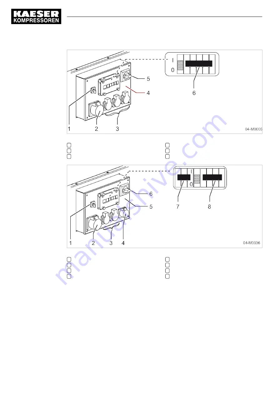
Fig. 21 Generator instrument panel - control box, 400 V, 3-phase
1
«Mode selector switch»
2
Three-phase power sockets
3
Single-phase power sockets
4
Generator control box
5
«Generator main switch»
6
«Safety cut-out» (with overcurrent release)
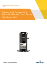
Fig. 22 Generator instrument panel - control box, 230 V, 3-phase
1
«Mode selector switch»
2
3-phase power sockets, 32 A
3
Single-phase power sockets
4
3-phase power sockets, 16 A
5
Generator control box
6
«Generator main switch»
7
«Safety cut-out»
8
«Safety cut-out» (with overcurrent release)
4.11.3 Note when operating the generator
Take note before switching in the generator:
When the network is fully loaded:
■ The power consumption values of simultaneous consumers are added.
■ The maximum continuous loading on the generator by connected consumers is limited by safety
cut-outs.
4
Design and Function
4.11 Generator option
52
Service Manual Screw Compressor
M135 SIGMA CONTROL MOBIL
No.: 9_6975 00 E


