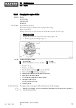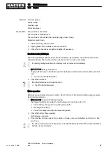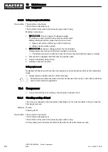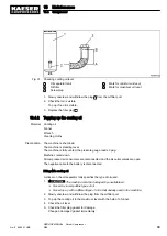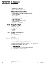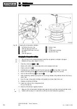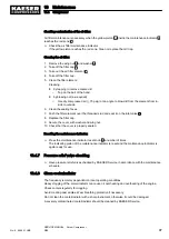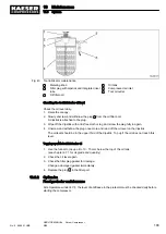
Checking contamination of the air filter:
Air filter maintenance is necessary when the yellow piston
10
inside the maintenance indicator
6
reaches the red zone
9
.
➤ Check the air filter maintenance indicator.
If the yellow piston reaches the red zone, Clean or replace the dirt trap.
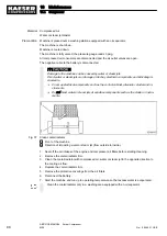
Cleaning the air filter:
1. Remove the wing nut
1
and washer
2
.
2. Take off the filter cap
3
.
3. Take out the air filter element
4
.
4. Take off the filter cap.
5. Clean the filter element:
Cleaning
■ by tapping to remove course dirt
─ Tap on the ball of the hand.
■ by blowing out (as required)
─ Use dry compressed air (≤ 75 psig) at an angle to blow dirt from the element from in‐
side to outside.
6. Clean the sealing faces.
7. Push the filter element over the threaded stud and seat it on the inlet valve
5
.
8. Replace the filter cap.
9. Secure the cover with washer and wing nut.
10. Check that the cover is properly seated.
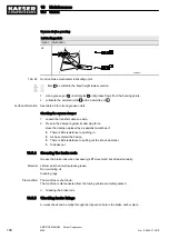
Resetting the maintenance indicator:
➤ Press the maintenance indicator reset knob
8
a number of times.
The indicating piston of the maintenance indicator is reset and the maintenance indicator is
again ready for use.
10.4.7 Pressure relief valve checking
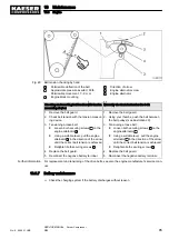
➤ Have pressure relief valves checked by KAESER Service in accordance with the maintenance
schedule.
10.4.8 Clean cooler/radiator
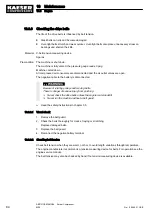
The frequency is mainly dependent on local operating conditions.
Heavy clogging of the cooler/radiator can cause oil overheating and overheating of the engine.
Check coolers regularly for clogging.
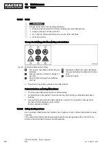
Avoid creating dust eddies. Wear breathing protection if necessary.
Do not clean the cooler/radiator with a sharp instrument, otherwise it could be damaged.
A severely contaminated cooler/radiator should be cleaned by KAESER Service.
10 Maintenance
10.4 Compressor
No.: 9_9446 01 USE
SERVICE MANUAL Screw Compressor
M26
97
Summary of Contents for M26
Page 1: ...SERVICE MANUAL Screw Compressor M26 No 9_9446 01 USE...
Page 191: ...13 Annex 13 3 Dimensional drawing No 9_9446 01 USE SERVICE MANUAL Screw Compressor M26 183...
Page 193: ...13 Annex 13 3 Dimensional drawing No 9_9446 01 USE SERVICE MANUAL Screw Compressor M26 185...
Page 194: ...13 Annex 13 4 Electrical Diagram No 9_9446 01 USE SERVICE MANUAL Screw Compressor M26 187...
Page 195: ...13 Annex 13 4 Electrical Diagram 188 SERVICE MANUAL Screw Compressor M26 No 9_9446 01 USE...
Page 196: ...13 Annex 13 4 Electrical Diagram No 9_9446 01 USE SERVICE MANUAL Screw Compressor M26 189...
Page 197: ...13 Annex 13 4 Electrical Diagram 190 SERVICE MANUAL Screw Compressor M26 No 9_9446 01 USE...
Page 198: ...13 Annex 13 4 Electrical Diagram No 9_9446 01 USE SERVICE MANUAL Screw Compressor M26 191...
Page 199: ...13 Annex 13 4 Electrical Diagram 192 SERVICE MANUAL Screw Compressor M26 No 9_9446 01 USE...
Page 200: ...13 Annex 13 4 Electrical Diagram No 9_9446 01 USE SERVICE MANUAL Screw Compressor M26 193...
Page 201: ...13 Annex 13 4 Electrical Diagram 194 SERVICE MANUAL Screw Compressor M26 No 9_9446 01 USE...

