4.4.2 MODULATING control
The control system regulates the volume of air generated to match the actual demand. The ma‐
chine keeps the working pressure constant by varying the volume of compressed air delivered,
thereby matching the air demand.
With the help of a mechanical control valve (the proportional controller), the opening and closing of
the inlet valve is continuously varied in relation to the actual air demand. The airend provides com‐
pressed air for connected consumers.
This stepless delivery regulation minimises fuel consumption of the engine. The load and fuel con‐
sumption of the engine rises and falls with the air demand.
4.5 Safety devices
4.5.1 Monitoring functions with shutdown
The following functions are monitored automatically.
■ Engine oil pressure
■ Coolant temperature
■ Airend discharge temperature
■ Engine alternator
The fuel stop device is activated when an alarm occurs. The engine comes to a stop and the
venting valve releases pressure from the machine.
4.5.2 Further safety devices
The following safety devices are provided and may not be modified in any way.
■ Pressure relief valve:
This valve protects the system from excessive pressure. It is factory set.
■ Enclosures and covers over moving parts and electrical connections:
These protect against accidental contact.
4.6 Options
4.6.1 Option oe
Environmental protection equipment
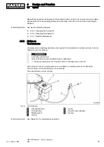
A "sealed floor pan" guarantees the leak-tightness of the bottom of the bodywork against leakage
of any operating fluids.
These may include:
■ Compressor cooling oil
■ Engine oil
■ Engine coolant
■ Fuel
■ Battery electrolyte
■ Tool oil (option)
4
Design and Function
4.5
Safety devices
30
SERVICE MANUAL Screw Compressor
M26
No.: 9_9446 01 USE
Summary of Contents for M26
Page 1: ...SERVICE MANUAL Screw Compressor M26 No 9_9446 01 USE...
Page 191: ...13 Annex 13 3 Dimensional drawing No 9_9446 01 USE SERVICE MANUAL Screw Compressor M26 183...
Page 193: ...13 Annex 13 3 Dimensional drawing No 9_9446 01 USE SERVICE MANUAL Screw Compressor M26 185...
Page 194: ...13 Annex 13 4 Electrical Diagram No 9_9446 01 USE SERVICE MANUAL Screw Compressor M26 187...
Page 195: ...13 Annex 13 4 Electrical Diagram 188 SERVICE MANUAL Screw Compressor M26 No 9_9446 01 USE...
Page 196: ...13 Annex 13 4 Electrical Diagram No 9_9446 01 USE SERVICE MANUAL Screw Compressor M26 189...
Page 197: ...13 Annex 13 4 Electrical Diagram 190 SERVICE MANUAL Screw Compressor M26 No 9_9446 01 USE...
Page 198: ...13 Annex 13 4 Electrical Diagram No 9_9446 01 USE SERVICE MANUAL Screw Compressor M26 191...
Page 199: ...13 Annex 13 4 Electrical Diagram 192 SERVICE MANUAL Screw Compressor M26 No 9_9446 01 USE...
Page 200: ...13 Annex 13 4 Electrical Diagram No 9_9446 01 USE SERVICE MANUAL Screw Compressor M26 193...
Page 201: ...13 Annex 13 4 Electrical Diagram 194 SERVICE MANUAL Screw Compressor M26 No 9_9446 01 USE...


