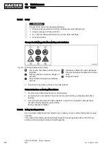
Engine casing fracture
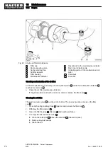
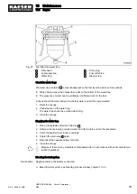
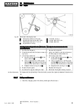
➤ Check coolant.
➤ Protect the coolant against frost.
➤ Top up as necessary.
2. Slowly open the cap on the coolant filler by a quarter to half of a turn to allow pressure to es‐
cape.
3. Then remove the filler cap completely.
4. Use the coolant tester as instructed by the manufacturer to test the coolant.
Change the coolant when the concentration of antifreeze is too low.
5. Mix the concentration of antifreeze as shown in the table.
Description
Antifreeze concentra‐
tion
[% vol.]
Water percentage
[% vol.]
Freezing point
[°F]
Minimum required anti‐
freeze concentration
40
60
−13
Minimum required anti‐
freeze concentration for
topping up
50
50
−35
Maximum permissible an‐
tifreeze concentration
55
45
−50
Tab. 60 Coolant frost protection
Topping up the coolant
Make sure that there is sufficient room for the coolant to expand when hot without overflow‐
ing.
1. Slowly open the cap on the coolant filler by a quarter to half of a turn to allow pressure to es‐
cape.
2. Then remove the filler cap completely.
3. Mix a quantity of coolant according to the table and top up to the mark.
The level should be between the marks.
4. Screw on the filler cap.
5. Reconnect the battery.
6. Start the engine and allow to idle for about 1 minute.
7. Stop the engine.
8. Check the coolant level.
Top up if the coolant level in the expansion tank has fallen.
Draining the coolant
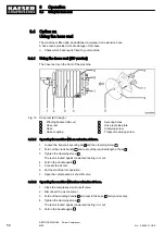
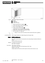
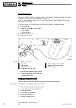
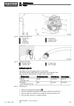
To catch any operating fluid leaks within the machine, the floor pan is equipped with an additional
oil-tight plug at the radiator drain hole.
The oil-tight plug must be removed before draining the coolant.
The radiator drain plug
3
can be reached from below through a hole in the floor pan.
10 Maintenance
10.3 Engine
72
SERVICE MANUAL Screw Compressor
M26
No.: 9_9446 01 USE
Summary of Contents for M26
Page 1: ...SERVICE MANUAL Screw Compressor M26 No 9_9446 01 USE...
Page 191: ...13 Annex 13 3 Dimensional drawing No 9_9446 01 USE SERVICE MANUAL Screw Compressor M26 183...
Page 193: ...13 Annex 13 3 Dimensional drawing No 9_9446 01 USE SERVICE MANUAL Screw Compressor M26 185...
Page 194: ...13 Annex 13 4 Electrical Diagram No 9_9446 01 USE SERVICE MANUAL Screw Compressor M26 187...
Page 195: ...13 Annex 13 4 Electrical Diagram 188 SERVICE MANUAL Screw Compressor M26 No 9_9446 01 USE...
Page 196: ...13 Annex 13 4 Electrical Diagram No 9_9446 01 USE SERVICE MANUAL Screw Compressor M26 189...
Page 197: ...13 Annex 13 4 Electrical Diagram 190 SERVICE MANUAL Screw Compressor M26 No 9_9446 01 USE...
Page 198: ...13 Annex 13 4 Electrical Diagram No 9_9446 01 USE SERVICE MANUAL Screw Compressor M26 191...
Page 199: ...13 Annex 13 4 Electrical Diagram 192 SERVICE MANUAL Screw Compressor M26 No 9_9446 01 USE...
Page 200: ...13 Annex 13 4 Electrical Diagram No 9_9446 01 USE SERVICE MANUAL Screw Compressor M26 193...
Page 201: ...13 Annex 13 4 Electrical Diagram 194 SERVICE MANUAL Screw Compressor M26 No 9_9446 01 USE...

