Maintenance
9 --- 50
5
6
6
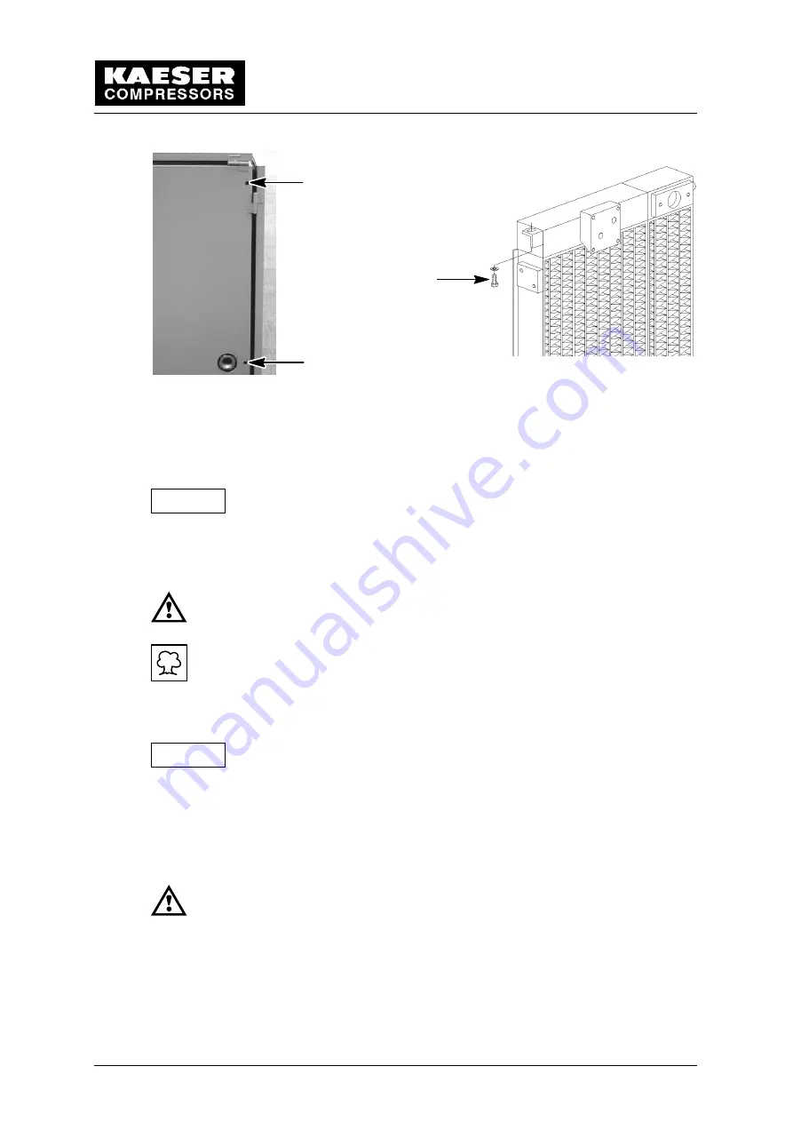
5 Hexagonal nut
6 Allen screw
Unscrew the hex bolt (5).
The hex socket head bolts (6) are located behind two protective caps.
Before unscrewing the two hex socket head bolts (6) prop up the com-
bination oil/air aftercooler.
Remove the protective caps and unscrew the two hex socket head bolts (6).
Take out the aftercooler.
Do not direct compressed air, water or steam jets toward any person.
These represent contained energy and as such, are dangerous to life.
The soiled cooler laminations may be cleaned with water or steam jet
only in designated cleaning areas with oil separators suited for such
purpose!
Clean the cooler laminations with compressed air, water or steam jet.
Seat the O -- rings correctly in the compressed air inlet of the oil/air
aftercooler during reassembly.
Reassemble in the reverse order.
See chapter 9.12 for topping off the oil.
Open the isolation shut ---off valve between the compressor and the compressed air
system.
Perform a test run
When the operating temperature is reached (see chapter 1.1), shut
down the compressor package (see chapter 8.3) and lock the main
disconnect in the ”off” position in accordance with applicable lock out/
tag out procedures (example: OSHA CFR 29 § 1910.147) to ensure the
compressor does not restart.
Afterwards, carry out a visual check for leaks.
Attention!
Attention!
Summary of Contents for SK 19
Page 10: ...Technical Specification 1 6 ...
Page 19: ...Construction and Operation 5 15 ...
Page 20: ...Construction and Operation 5 16 ...
Page 64: ...Appendix 11 60 11 Appendix 11 1 Wiring Diagram ...
Page 65: ......
Page 66: ......
Page 67: ......
Page 68: ......
Page 69: ......
Page 70: ......
Page 71: ......
Page 72: ......
Page 73: ......
Page 74: ......
Page 75: ......
Page 76: ......
Page 77: ......
Page 78: ......
Page 79: ......
Page 80: ......
Page 81: ...Appendix 11 77 11 2 Spare Parts List ...
Page 82: ......
Page 83: ......
Page 84: ......
Page 85: ......


