Technical Specification
1 --- 2
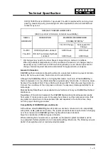
Maximum dual element time -- delay fuses are selected according to
1996 N.E.C. Article 240 -- 6, 430 -- 52 and Tables 430 -- 148 & 150.
Select multi-- strand copper core wire at 40
C ambient temperature
according to 1996 N.E.C. 110 -- 14(c), 220 -- 3, 310 -- 15, Table 310 -- 16,
430 -- 6, 430 -- 22 and Tables 430 -- 148 & 150.
For electrical power supply please refer to chapter 2.3 and 6.3
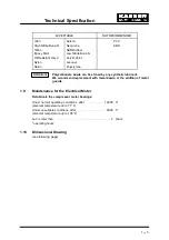
1.5
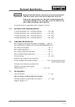
Set Point of the Safety Relief Valve
110 psig Compressor Unit --- Activating pressure
140 psig
. . . . . . . .
125 psig Compressor Unit --- Activating pressure
155 psig
. . . . . . . .
145 psig Compressor Unit --- Activating pressure
175 psig
. . . . . . . .
190 psig Compressor Unit --- Activating pressure
230 psig
. . . . . . . .
1.6
Installation Requirements
Max. height above sea level of the place of installation
3000 ft.
. .
(for all heights above please contact authorized KAESER distributor)
Min. ambient temperature
40
E
F
. . . . . . . . . . . . . . . . . . . . . . . . . . . . .
Max. ambient temperature
105
E
F
. . . . . . . . . . . . . . . . . . . . . . . . . . . .
Min. cooling air/inlet air temperature
40
E
F
. . . . . . . . . . . . . . . . . . . .
Max. cooling air/inlet air temperature
105
E
F
. . . . . . . . . . . . . . . . . . .
Air inlet opening
2.2 sq.ft.
. . . . . . . . . . . . . . . . . . . . . . . . . . . . . . . . . . . . .
Exhaust air for solution A (see chapter 6.1):
Forced ventilation with exhaust ventilator
1470 cfm at static pressure of
. . . . . . . . . . . . . .
0.4 inches water column
Exhaust air for solution B (see chapter 6.1):
Exhaust air used for space heating:
Heating duct w x h
7 3/4” x 14”
. . . . . . . . . . . . . . . . . . . . . . . . . . . .
1.7
Oil Capacities
Total oil capacities
1.3 gal
. . . . . . . . . . . . . . . . . . . . . . . . . . . . . . . . . . .
After oil change or after long period of storage
Quantity required for prelubrication of the airend
0.1 quart
. . . . . . . . .
(Refer to chapter 7.7.1)
Attention!
Summary of Contents for SM 8
Page 9: ...Technical Specification 1 6...
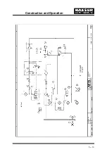
Page 16: ...Construction and Operation 5 13...
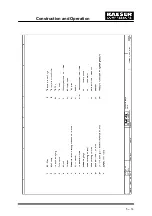
Page 17: ...Construction and Operation 5 14...
Page 54: ...Appendix 11 51 11 Appendix 11 1 Wiring Diagram...
Page 55: ......
Page 56: ......
Page 57: ......
Page 58: ......
Page 59: ......
Page 60: ......
Page 61: ......
Page 62: ......
Page 63: ......
Page 64: ......
Page 65: ......
Page 66: ......
Page 67: ......
Page 68: ......
Page 69: ......
Page 74: ...SM 8 SM 11 A 08 B 07 C 14 D 11...
Page 76: ......
Page 78: ......
Page 80: ......
Page 82: ......


