background image

M-485B Horn Signal Controller Instructions 


Rev. 4/12/2022 

www.kahlenberg.com


Customer Support: 1-920-793-4507 


Location and Mounting: 

The M-485B Enclosure must be installed in a location protected from weather, inside the main 

control console, within appx. 2-1/2 feet of the intended switch location.  Three feet (0.9M) of 

switch cable harness is provided.   Extra length of this cable can be provided upon request.  See 

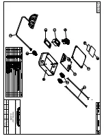
drawing 3-7575 for mounting hole size and locations on the enclosure. 

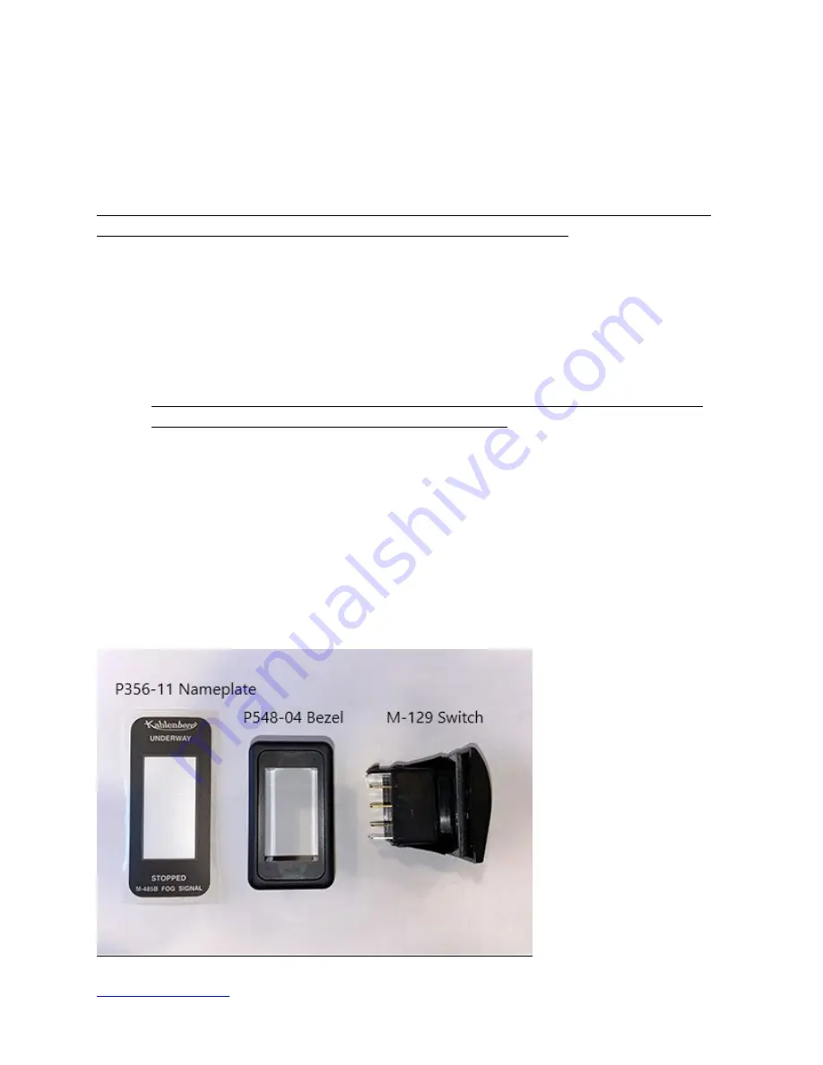
The M-129 Rocker Switch is intended for installation in the P548-04 mounting bezel, which is 

installed in the console switch panel.  The P548-04 mounting bezel allows for installation in 

panel material thickness of .062” (1.57mm) to .375” (9.52 mm) thickness.


1.)


The hole in the panel should be cut per the switch cutout depicted on drawing 3-7575.   

NOTE:  If the switch is to be used without the P548-04 mounting bezel, the hole will 

need to be smaller!   Verify dimensions before cutting! 

2.)


Clean the console panel surface.  Remove adhesive backing, align and install the P356-

11 Nameplate on the panel.  

3.)


Verify that the wiring harness switch connections can be pulled up through the panel to 

connect the switch. 

4.)


Apply marine silicone sealant to the panel surface to seal the bezel. 

5.)


Mount the P548-04 Bezel in the hole and wipe off excess sealant. 

6.)


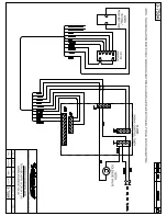
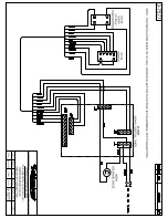
Bring the wire harness from the M-485B through the hole and make connections to the 

M-129 Switch per wiring diagram enclosed. 

7.)


Verify correct operation in the following sections before installing M-129 Switch into 

P548-04 Bezel.   Once the switch is installed in the bezel it is very difficult to remove. 


Summary of Contents for M-485B

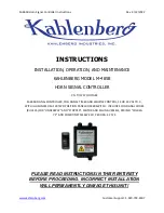
Page 1: ...TI 37575 DC ABC M 485B SIGNAL CONTROLLER FOG SIGNAL TIMER AND WHISTLE CONTROL 12 OR 24 VOLT D C WITH ILLUMINATED M 129 TWO POSITION PANEL ROCKER SWITCH INCLUDES FOG SIGNAL CODES RULE 35 FOR UNDERWAY A...

Page 2: ...ting 9 Drawings 10 15 WARNING This instruction manual contains important instructions for operating this product Read this manual thoroughly before operating the product Failure to properly follow all...

Page 3: ...ate control for automating sound signals in conditions of restricted visibility fog signals as prescribed by International Navigation Rules IMO COLREGS Part D Rule 35 The M 485B will output signals fo...

Page 4: ...rescribed in paragraphs a or b of this Rule sound at intervals of not more than 2 minutes three blasts in succession namely one prolonged followed by two short blasts PACKAGE CONTENTS The M 485B Horn...

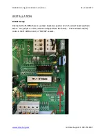
Page 5: ...r Support 1 920 793 4507 INSTALLATION Initial Setup Internal to the M 485A there is a jumper located at position J2 on the circuit board as shown below The jumper is in this position as shipped from t...

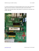
Page 6: ...0 793 4507 To change the M 485B output to the restricted visibility codes for SAIL vessels gently pull the jumper up off the pins and move it to disconnect the jumper circuit as shown below NOTE When...

Page 7: ...75 9 52 mm thickness 1 The hole in the panel should be cut per the switch cutout depicted on drawing 3 7575 NOTE If the switch is to be used without the P548 04 mounting bezel the hole will need to be...

Page 8: ...location on J1 and install it in terminal J8 3rd terminal location right next to the existing red horn cable wire 4 Make connections according to wiring diagram 3 7597 or wiring diagram 3 7582 if the...

Page 9: ...on on the vessel is a standard single pole switch the horn should sound when it is depressed but the automated signal code will continue to sound the horn uninterrupted on the M 485B MAINTENANCE The M...

Page 10: ...B is sending current to solenoid valve but air horn is not sounding Solenoid valve body is installed backwards in air line Verify solenoid valve installation is correct An arrow on the valve body indi...

Page 11: ......

Page 12: ......

Page 13: ......

Page 14: ......

Page 15: ......

Page 16: ......

Reviews: