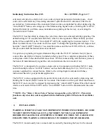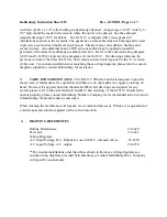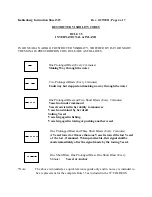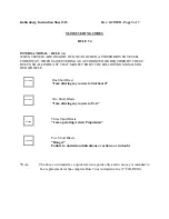
Kahlenberg Instruction Sheet 323
Rev. 6/29/2011, Page 3 of 7
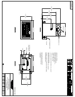
with four (4) #8 x 1-1/4" self clinching studs already attached. An opening of 4-3/8" wide by 2-
7/8" high should be made in the console where the unit is to be placed. See the enclosed
template drawing 2-5437 for details. The M-511C is shipped with 1 loose gasket for
installations exposed to the elements. The gasket has a removable adhesive backing and is used
to provide a seal between the Bezel and Console. Simply remove the adhesive backing and
secure in place. An additional bead of RTV silicone sealant may be applied around the
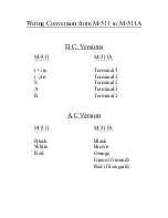
perimeter of the Bezel for additional weather protection. Refer to the enclosed wiring diagram
3-6238 and 3-6399 for typical wiring diagrams for the M-511C. The drawings reference the
previous version of the timer (M-511A), but remain accurate in all respects for the “C” revision
of this unit. For custom installations not matching these wiring diagrams, please refer to custom
diagrams supplied or contact Kahlenberg for assistance.
5)
CARE AND MAINTENANCE
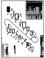
- The M-511C Whistle Control is designed to provide
many years of maintenance free operation and there are no spare parts we suggest you keep on
hand. However if any parts listed on the attached Parts List drawings are required for any
reason, please refer to the associated part number when ordering. If the M-511C should fail to
operate properly please contact Kahlenberg Brothers Company for recommended action or return
to Kahlenberg for prompt analysis and repair.
When cleaning the membrane switch panel, we recommend the use of Windex (or equivalent) or
a mild soap/water solution applied with a soft cotton cloth.
6)
DRAWING REFERENCES
Outline
Dimensions:
#3-6429
Parts
List:
#3-6431
Wiring Diagrams:
A.C. Input Voltage, D.C. Output, for use with D.C. solenoid valves:
#3-6399
A.C.
Input
Voltage,
A.C.
output:
#3-6238
**For custom installations other than those shown in the above wiring diagrams see
custom wiring diagrams provided by Kahlenberg or contact Kahlenberg Bros. Company
with specific requirements.


