Electrical Control Function
Electrical Control System
133
24~60K
T 4
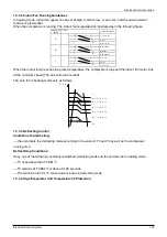
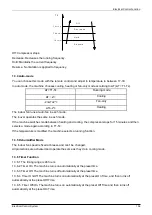
1.3.2.3 Indoor Fan Running Guidelines
In cooling mode, the indoor fan runs continuously and You can select the following speeds: high, medium,
low, auto or silent. When the compressor is running, The indoor fan is regulated as illustrated as in the
following figure:
Setting fan
speed
T1-Td
℃
(°F)
Actual fan speed
H
H+(H+=H+G)
A
H
(
=H
)
B
H-
(
H-=H-G)
C
M
M+(M+=M+Z)
D
M(M=M)
E
M-(M-=M-Z)
F
L
L+(L+=L+D)
G
L(L=L)
H
L-(L-=L-D)
I
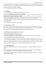
The auto fan in cooling mode acts as follows:
T 1 - T d
H
( H - L ) * 0 . 7 5 + L
( H - L ) * 0 . 5 + L
( H - L ) * 0 . 2 5 + L
L
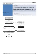
1.3.2.3 Evaporator Low Temperature T2 Protection.
---T2<0
℃
, the compressor stops and restarts only when T2
≥
5
℃
.
---0
℃
≤T2<4
℃
, the compressor frequency is limited and decreases to a lower level
---4
℃
≤T2<7
℃
, the compressor maintains its current frequency.
---T2>7
℃
, the compressor frequency is not limited.
A +
A
B
C
D
E
F
G
H
I
a
b
c
d
e
Summary of Contents for KOB30U-18HFN32
Page 1: ...i KAISAI SUPER DC INVERTER SERIES Service Manual 2019 ...
Page 12: ...Indoor Units 11 Service Space 3 Service Space 1000m m 1000mm 1000m m 1000m m ...
Page 15: ...Indoor Units 14 Wiring Diagrams ...
Page 20: ...Indoor Units 19 Air Velocity Distributions Reference Data 30 42K Cooling Heating ...
Page 21: ...Indoor Units 20 Air Velocity Distributions Reference Data 48 55K Cooling Heating ...
Page 26: ...Indoor Units 25 Field Wiring 10 Field Wiring KCD 24HRF32 KCD 36HRF32 ...
Page 27: ...Indoor Units 26 Field Wiring KCD 48HRF32 KCD 55HRF32 ...
Page 49: ...Indoor Units 48 Field Wiring 10 Field Wiring 18k 55k ...
Page 53: ...Indoor Units 52 Service Space 3 Service Space ...
Page 55: ...Indoor Units 54 Wiring Diagrams ...
Page 72: ...Indoor Units 71 Service Space 3 Service Space ...
Page 73: ...Indoor Units 72 Wiring Diagrams 4 Wiring Diagrams KCA3U 12HRF32X ...
Page 82: ...Outdoor Units Outdoor Units 82 10 Field Wiring KCA3U 12HRF32X ...
Page 87: ...Outdoor Units 87 Wiring Diagrams 3 Wiring Diagrams KOB30 12HFN32X ...
Page 88: ...Outdoor Units 88 Wiring Diagrams KOB30U 18HFN32 ...
Page 89: ...Outdoor Units 89 Wiring Diagrams KOCA30U 24HFN32 ...
Page 90: ...Outdoor Units 90 Wiring Diagrams ...
Page 91: ...Outdoor Units 91 Wiring Diagrams KOD30U 36HFN32 ...
Page 92: ...Outdoor Units 92 Wiring Diagrams ...
Page 93: ...Outdoor Units 93 Wiring Diagrams KOE30U 48HFN32 KOE30U 55HFN32 ...
Page 118: ...Installation 119 Refrigerant pipe installation ...
Page 183: ...Controller Electrical Control System 184 ...
Page 184: ...Controller Electrical Control System 185 ...

