Electrical Control Function
Electrical Control System
139
digits.
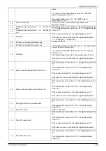
For example, if the digital display shows “0.5", the IGBT
radiator temperature is 105
℃
.
If the digital display shows “1.6", the IGBT radiator
temperature is 116
℃
.
18
Indoor unit number
The indoor unit can communicate with outdoor unit.
General: 1, Twins: 2
19
Condenser pipe temperature
unit
of
#1 indoor If the temperature is lower than 0
℃
, the digital display shows
“0”. If the temperature is higher than 70
℃
, the digital display
shows “70.”
If the capacity demand is 0, the digital display shows “0”.
If the indoor unit is not connected, the digital display shows:
“――”(heating T2
,
cooling T2B)
20
Condenser pipe temperature
unit
of
#2 indoor
21
Reserved
22
#1 Indoor unit capacity demand code
Actual data*HP*10
If a capacity demand code is higher than 99, the digital display
shows single and double digits.
For example, if the digital
display reads “5.0”, the capacity
demand is 15.
If the digital display shows “60”, the capacity demand is 6.0.
If the indoor unit is not connected, the digital display shows:
“――”
23
#2 Indoor unit capacity demand code
24
Reserved
25
Indoor room temperature of #1 indoor unit
If the temperature is lower than -9
℃
, the digital display shows
“9”.
If the temperature is higher than 70
℃
, the digital display
shows “70”.
If the capacity demand is 0, the digital display shows “0”.
If the indoor unit is not connected, the digital display shows:
“――”
26
Indoor room temperature of #2 indoor unit
If the temperature is lower than 0
℃
, the digital display shows
“0”.
If the temperature is higher than 70
℃
, the digital display
shows
“70”.
If the capacity demand is 0, the digital display shows “0".
If the indoor unit is not connected, the digital display shows:
“――”
27
Average of indoor room temperature
If the temperature is lower than 0
℃
, the digital display shows
“0”.
If the temperature is higher than 70
℃
, the digital display
shows “70”.
28
Shutdown cause
Refer to Appendix
29
T2B of #1 indoor unit
If the temperature is lower than -9
℃
, the digital display shows
“9”.
If the temperature is higher than 70
℃
, the digital display
shows “70”.
If the capacity demand is 0, the digital display shows “0”.
If the indoor unit is not connected, the digital display shows:
“――”
30
T2B of #2 indoor unit
If the temperature is lower than 0
℃
, the digital display shows
“0”.
If the temperature is higher than 70
℃
, the digital display
shows “70”.
Summary of Contents for KOB30U-18HFN32
Page 1: ...i KAISAI SUPER DC INVERTER SERIES Service Manual 2019 ...
Page 12: ...Indoor Units 11 Service Space 3 Service Space 1000m m 1000mm 1000m m 1000m m ...
Page 15: ...Indoor Units 14 Wiring Diagrams ...
Page 20: ...Indoor Units 19 Air Velocity Distributions Reference Data 30 42K Cooling Heating ...
Page 21: ...Indoor Units 20 Air Velocity Distributions Reference Data 48 55K Cooling Heating ...
Page 26: ...Indoor Units 25 Field Wiring 10 Field Wiring KCD 24HRF32 KCD 36HRF32 ...
Page 27: ...Indoor Units 26 Field Wiring KCD 48HRF32 KCD 55HRF32 ...
Page 49: ...Indoor Units 48 Field Wiring 10 Field Wiring 18k 55k ...
Page 53: ...Indoor Units 52 Service Space 3 Service Space ...
Page 55: ...Indoor Units 54 Wiring Diagrams ...
Page 72: ...Indoor Units 71 Service Space 3 Service Space ...
Page 73: ...Indoor Units 72 Wiring Diagrams 4 Wiring Diagrams KCA3U 12HRF32X ...
Page 82: ...Outdoor Units Outdoor Units 82 10 Field Wiring KCA3U 12HRF32X ...
Page 87: ...Outdoor Units 87 Wiring Diagrams 3 Wiring Diagrams KOB30 12HFN32X ...
Page 88: ...Outdoor Units 88 Wiring Diagrams KOB30U 18HFN32 ...
Page 89: ...Outdoor Units 89 Wiring Diagrams KOCA30U 24HFN32 ...
Page 90: ...Outdoor Units 90 Wiring Diagrams ...
Page 91: ...Outdoor Units 91 Wiring Diagrams KOD30U 36HFN32 ...
Page 92: ...Outdoor Units 92 Wiring Diagrams ...
Page 93: ...Outdoor Units 93 Wiring Diagrams KOE30U 48HFN32 KOE30U 55HFN32 ...
Page 118: ...Installation 119 Refrigerant pipe installation ...
Page 183: ...Controller Electrical Control System 184 ...
Page 184: ...Controller Electrical Control System 185 ...


