Controller
Electrical Control System
182
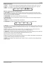
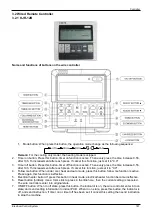
8. Adjust button: Set indoor temperature up. If press and hold on, it will increase at 1degree per 0.5
second.
9. Adjust button: Set indoor temperature down. if press and hold on, it will decrease at 1degree per 0.5
Second.
10. Swing button: First press, start swing function; second press, stop swing. (Match to some model with
swing function).
11. Economy operation button: press this button, the indoor unit operates in economy mode, press again,
exit this mode (it may be ineffective for some models)
12. Fan speed button: press this button consecutively; the fan speed will circle as follow:
13. Lock button (hidden): When you push the LOCK button, all current settings are locked in and the wire
controller does not accept any operation except that of the LOCK button. Use the lock mode when you
want to prevent setting from being changed accidentally or play fully. Push the LOCK button again when
you want to cancel the LOCK mode.
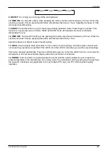
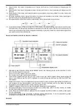
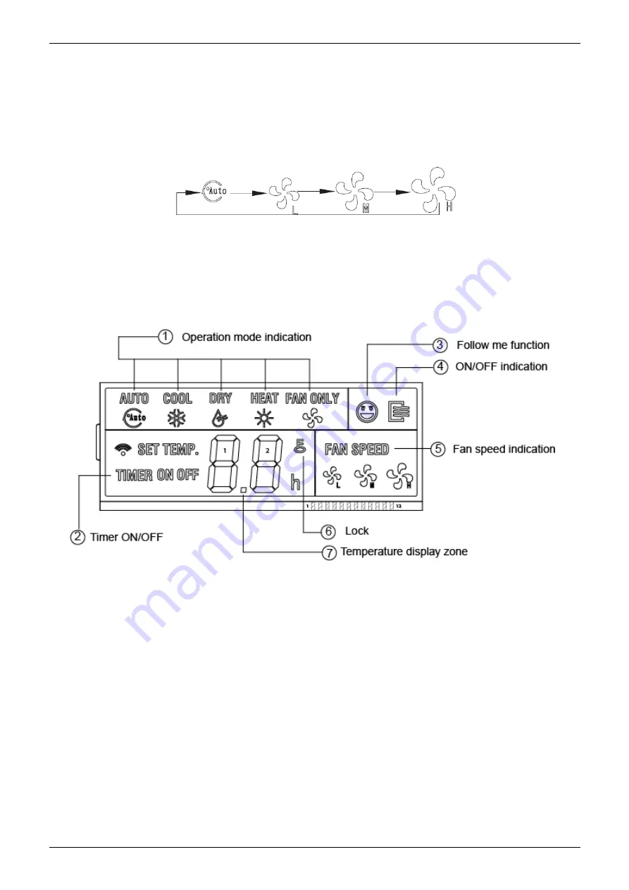
Name and function of LCD on the wire controller
1.
Operation mode indication: When press” MODE” button, the following mode can be selected in circle.
Auto Cool Dry Heat Fan only Auto.
Auto
→
Cool
→
Dry
→
Heat
→
Fan only
→
Auto
For cooling only model, heat mode is skipped.
2. Timer: When adjust setting on
time or only on time is set, the “ON” is lighted. When adjust setting off
time or only off time is set, the” OFF" is lighted. If on and off timer are both set, the “ON” and “OFF” are
both lighted.
3. Follow me function: There is a temperature sensor inside the wire controller, after setting temperature, it
will compare the two temperatures, and the space of wire controller will be the same as setting
temperature. It is available under cooling, heating, auto mode.
4
ON/OFF indication: When it is on, the icon display, otherwise it is extinguished.
5. Fan speed indication: There are four fan modes: low, middle, high, auto. For some models, no middle
fan then the middle fan is seen as high speed.
6. Lock: When the "LOCK" button is pressed, the icon appears and other buttons is unable, press again,
the icon disappears.
7. Temperature display zone: Generally it displays setting temperature; it can be adjusted by press
temperature button
▲and▼
.But in fan mode, no display here.
Remark:
Summary of Contents for KOB30U-18HFN32
Page 1: ...i KAISAI SUPER DC INVERTER SERIES Service Manual 2019 ...
Page 12: ...Indoor Units 11 Service Space 3 Service Space 1000m m 1000mm 1000m m 1000m m ...
Page 15: ...Indoor Units 14 Wiring Diagrams ...
Page 20: ...Indoor Units 19 Air Velocity Distributions Reference Data 30 42K Cooling Heating ...
Page 21: ...Indoor Units 20 Air Velocity Distributions Reference Data 48 55K Cooling Heating ...
Page 26: ...Indoor Units 25 Field Wiring 10 Field Wiring KCD 24HRF32 KCD 36HRF32 ...
Page 27: ...Indoor Units 26 Field Wiring KCD 48HRF32 KCD 55HRF32 ...
Page 49: ...Indoor Units 48 Field Wiring 10 Field Wiring 18k 55k ...
Page 53: ...Indoor Units 52 Service Space 3 Service Space ...
Page 55: ...Indoor Units 54 Wiring Diagrams ...
Page 72: ...Indoor Units 71 Service Space 3 Service Space ...
Page 73: ...Indoor Units 72 Wiring Diagrams 4 Wiring Diagrams KCA3U 12HRF32X ...
Page 82: ...Outdoor Units Outdoor Units 82 10 Field Wiring KCA3U 12HRF32X ...
Page 87: ...Outdoor Units 87 Wiring Diagrams 3 Wiring Diagrams KOB30 12HFN32X ...
Page 88: ...Outdoor Units 88 Wiring Diagrams KOB30U 18HFN32 ...
Page 89: ...Outdoor Units 89 Wiring Diagrams KOCA30U 24HFN32 ...
Page 90: ...Outdoor Units 90 Wiring Diagrams ...
Page 91: ...Outdoor Units 91 Wiring Diagrams KOD30U 36HFN32 ...
Page 92: ...Outdoor Units 92 Wiring Diagrams ...
Page 93: ...Outdoor Units 93 Wiring Diagrams KOE30U 48HFN32 KOE30U 55HFN32 ...
Page 118: ...Installation 119 Refrigerant pipe installation ...
Page 183: ...Controller Electrical Control System 184 ...
Page 184: ...Controller Electrical Control System 185 ...

