background image

Indoor Units 

70 

Dimensions 


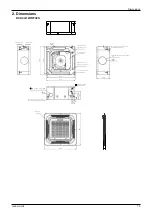
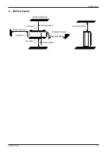
2. Dimensions 

KCA3U-12HRF32X 


L i q u i d  s i d e 


G a s s i d e 


B o d y 


W i r i n g c o n n e c t i o n p o r t 


l ) 


2 6 0  


2- 

-  1 5 0 D i s t r i b u t i o n d u c t 


2 - 1 7 0  


P a n e l 

5 0  

6 4 7  

D r a i n h o l e 

( f o r S e r v i c e ) 

E - p a r t s b o x 

4 - S c r e w h o l e 

( f o r i n s t a l l  p a n e 

4 - i n s t a l l  h a n g e r 

5 4 5  


5 7 0  

3 2 D r a i n p i p e 

6 5   F r e s h   a i r  i n t a k e 


7 5  

W i r i n g c o n n e c t i o n p o r t 

4 2  

6 8  

5

 7

 0


5

 2

 3


4

 4


1

 2

 6


1

 5

 7


6

 4

 7


Summary of Contents for KOB30U-18HFN32

Page 1: ...i KAISAI SUPER DC INVERTER SERIES Service Manual 2019 ...

Page 2: ...Information 1 Part 2 Indoor Units 5 Part 3 Outdoor Units 83 Part 4 Installation 99 Part 5 Electrical Control System 129 The specifications designs and information in this book are subject to change without notice for product improvement ...

Page 3: ...General Information General Information 1 Part 1 General Information 1 Model List 2 2 External Appearance 3 2 1 Indoor Units 3 2 2 Outdoor Units 3 ...

Page 4: ...oling and heating 1 2 Outdoor Units Universal Outdoor unit Model Compressor type Compressor Brand Matched indoor units KOB30U 18HFN32 Rotary GMCC KTI 18HWF32 KUE 18HRF32 KOCA30U 24HFN32 Rotary GMCC KCD 24HRF32 KTI 24HWF32 KUE 24HRF32 KOD30U 36HFN32 Rotary GMCC KCD 36HRF32 KTI 36HWF32 KUE 36HRF32 KOE30U 48HFN32 Rotary GMCC KCD 48HRF32 MTI 48HWF32 KUE 48HRF32 KOE30U 55HFN32 Rotary GMCC KCD 55HRF32 K...

Page 5: ...al Information 3 External Appearance 2 External Appearance 2 1 Indoor Units Super slim cassette Duct Ceiling Floor Compact Four way cassette 2 2 Outdoor Units Single fan outdoor unit Double fan outdoor unit ...

Page 6: ...Indoor Units Indoor Units 5 Part 2 Indoor Units Super Slim Cassette Type 6 A6 Duct Type 27 Ceiling Floor Type 50 Compact Four way Cassette Type 69 ...

Page 7: ...lim Cassette Type 1 Features 7 2 Dimensions 10 3 Service Space 11 4 Wiring Diagrams 12 5 Air Velocity Distributions Reference Data 18 6 Electric Characteristics 21 7 Sound Levels 22 8 Accessories 23 9 The Specification of Power 24 10 Field Wiring 25 ...

Page 8: ... air quality more healthy and comfortable Ventilation motor is optional to increase the effect of fresh air 1 3Optional ionizer generator Ionizer generator is optional to get refreshing air to your room Ionizer can be switched on or off by remote controller When pressing the Clean Air button on the remote controller Ionizer will work and the indicator light on display board will shine 1 4 External...

Page 9: ...venient to repair or replace the draining pump Built in draining pump to make sure condensed water drain out reliably 1 6Terminals for alarm lamp and long distance on off controller connection are standard Reserve terminals for the connection of alarm lamp and long distance on off controller more human control ...

Page 10: ...ins Combination 24k The units can be installed as Twin systems one outdoor unit can connect with two indoor units The indoor units can be combined in any of the different available ratings Long distance on off controller Alarm lamp ...

Page 11: ... 6 91 W i r i n g c o n n e c t i o n p o r t S e r v ic e h o le fo r d r a in in g p u m p B 32 D r a i n h o l e T e s t m o u t h T e s t c o v e r B 6 8 0 8 4 0 D D 196 C A A 92 92 92 92 P a n e l 950 5 5 Unit mm Model A B C D KCD 24HRF32 KCD 36HRF32 160 95 245 60 KCD 48HRF32 KCD 55HRF32 160 95 287 60 92 92 92 92 A A D D 780 D D B B 780 80 840 950 A A 90 132 92 92 92 92 135 ...

Page 12: ...Indoor Units 11 Service Space 3 Service Space 1000m m 1000mm 1000m m 1000m m ...

Page 13: ...remote switch on CLOSE the unit would be on 4 When close open the remote switch the unit would be responded the demand within 2 seconds 5 When the remote switch on You can use remote controller wire controller to select the mode what you want when the remote switch off the unit would not respond the demand from remote controller wire controller When the remote switch off but the remote controller ...

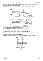
Page 14: ... 5A 3 When the unit occurs the problem the relay would be closed then ALARM works C For new fresh motor terminal port CN8 1 Connect the fan motor to the port no need care L N of the motor 2 The output voltage is the power supply 3 The fresh motor cannot excess 200W or 1A follow the smaller one 4 The new fresh motor will be worked when the indoor fan motor work when the indoor fan motor stops the n...

Page 15: ...Indoor Units 14 Wiring Diagrams ...

Page 16: ...ding to EEROM setting reserved for special customizing T 2 T E L 0 1 6 T E L 0 1 4 T E L 0 1 2 T E L 0 1 0 T E L 0 8 T E L 0 6 S e t t i n g f a n s p e e d H M M L S u p e r s l o w F a n o f f T E L 0 1 2 T E L 0 1 0 T E L 0 8 T E L 0 6 T E L 0 4 B Micro switch SW2 is for selection of indoor FAN ACTION if room temperature reaches the setpoint and the compressor stops Range OFF in 127s Keep runni...

Page 17: ...ithout difference Slave E Micro switch SW6 is for selection of temperature compensation in heating mode This helps to reduce the real temperature difference between ceiling and floor so that the unit could run properly If the height of installation is lower smaller value could be chosen Range 6oC 4oC 2oC E function reserved for special customizing F Micro switch S1 and dial switch S2 are for addre...

Page 18: ...rom 18K to 55K This ENC1 setting will tell the main program what size the unit is NOTE Usually there is glue on it because the switch position cannot be changed at random unless you want to use this PCB as a spare part to use in another unit Then you have to select the right position to match the size of the unit ...

Page 19: ...Indoor Units 18 Air Velocity Distributions Reference Data 5 Air Velocity Distributions Reference Data 24K Cooling Heating ...

Page 20: ...Indoor Units 19 Air Velocity Distributions Reference Data 30 42K Cooling Heating ...

Page 21: ...Indoor Units 20 Air Velocity Distributions Reference Data 48 55K Cooling Heating ...

Page 22: ...lectric Characteristics Model Indoor Unit Power Supply Hz Voltage Min Max MFA KCD 24HRF32 50 220 240V 198V 254V 10 KCD 36HRF32 50 220 240V 198V 254V 10 KCD 48HRF32 50 220 240V 198V 254V KCD 55HRF32 50 220 240V 198V 254V Notes MFA Max Fuse Amps A ...

Page 23: ...r Units 22 Sound Levels 7 Sound Levels Model Noise Power dB A Noise level dB A H M L KCD 24HRF32 57 47 43 40 KCD 36HRF32 60 52 49 46 KCD 48HRF32 69 52 50 49 KCD 55HRF32 65 53 51 48 1 4 m M i c r o p h o n e ...

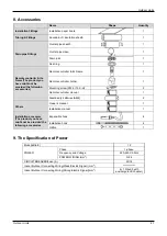
Page 24: ...eal ring 1 Remote controller Its Frame The product you have might not be provided the following accessories Remote controller Its Frame 1 Remote controller holder 1 Mounting screw ST2 9 10 C H 2 Remote controller manual 1 Alkaline dry batteries AM4 2 Others Owner s manual 1 Installation manual 1 Installation accessory The product you have might not be provided the following accessories Expansible ...

Page 25: ...ary electric heater 3 1 0 3 2 5 with auxiliary electric heater CIRCUIT BREAKER Fuse A 15 10 15 10 Outdoor Power Phase 1 phase 3 phase 3 phase Frequency Voltage and 220 240V 50Hz 380 415V 50Hz 380 415V 50Hz POWER mm2 WIRING 3 2 5 5 2 5 5 2 5 CIRCUIT BREAKER Fuse A 25 20 25 20 30 25 Indoor Outdoor Connecting Wiring Weak Electric Signal mm2 2 0 2 2 0 2 2 0 2 Indoor Outdoor Connecting Wiring Strong El...

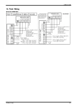
Page 26: ...Indoor Units 25 Field Wiring 10 Field Wiring KCD 24HRF32 KCD 36HRF32 ...

Page 27: ...Indoor Units 26 Field Wiring KCD 48HRF32 KCD 55HRF32 ...

Page 28: ... Type A6 Duct Type 1 Features 28 2 Dimensions 31 3 Service Space 32 4 Wiring Diagrams 33 5 Static Pressure 39 6 Electric Characteristics 45 7 Sound Levels 46 8 Accessories 47 9 The Specification of Power 48 10 Field Wiring 49 ...

Page 29: ... 48K unit 300mm 1 3 Constant air volume control For ordinary duct when the static pressure exceeds the expected range it is fairly difficult even for an experienced installer to calculate and adjust the air volume precisely With constant air volume control technology the duct will automatically adjusts to perfect static pressure and keep constant air volume 1 4 Flexible Air Intake Way Bottom side ...

Page 30: ...d from the inside by vacuum 1 7 Fresh air intake function Optional Install one duct from the reserved fresh air intake to outdoor Continually inhale the fresh air to improve the quality of the indoor air fulfills air quality more healthy and comfortable A ventilation motor provided by the installer can be installed inside the fresh air duct to improve the fresh air volume There are reserved ports ...

Page 31: ...Indoor Units 30 Features 1 8 Built in drain pump Optional Built in drain pump can lift the water to 750mm upmost which widens the drainage piping range Max 750mm ...

Page 32: ...0 926 50 175 1001 228 5 1140 598 80 150 130 155 inch 43 31 9 80 30 47 27 56 5 51 36 46 1 97 6 89 39 41 8 98 0 20 44 88 23 54 3 15 5 91 5 12 6 10 36 mm 1360 249 774 700 140 1186 50 175 1261 228 5 1400 598 80 150 130 155 inch 53 54 9 80 30 47 27 56 5 51 46 69 1 97 6 89 49 65 8 98 0 20 55 12 23 54 3 15 5 91 5 12 6 10 48 55 mm 1200 300 874 800 123 1044 50 227 1101 280 5 1240 697 80 150 185 210 inch 47...

Page 33: ...Indoor Units 32 Service Space 3 Service Space Ensure enough space required for installation and maintenance ...

Page 34: ...Indoor Units 33 Wiring Diagrams 4 Wiring Diagrams KTI 18HWF32 KTI 24HWF32 KTI 36HWF32 KTI 48HWF32 KTI 55HWF32 ...

Page 35: ... need care L N of themotor 2 The output voltage is the power supply 3 The fresh motor cannot excess 200W or 1A follow the smallerone 4 The new fresh motor will be worked when the indoor fan motor work when the indoor fan motor stops the new fresh motor would be stopped 5 When the unit enter force cooling mode or capacity testing mode the fresh motor isn t work C B A ...

Page 36: ...nector of J7 1 Remove the short connector of J7 when you use ON OFF function 2 When remote switch off OPEN the unit would be off 3 When remote switch on CLOSE the unit would be on 4 When close open the remote switch the unit would be responded the demand within 2 seconds 5 When the remote switch on You can use remote controller wire controller to select the mode what you want when the remote switc...

Page 37: ...5 T E 1 T E L 0 1 3 T E 1 S e t t i n g f a n s p e e d H M M L S u p e r s l o w F a n o f f T E L 0 1 8 T E 1 T E L 0 1 6 T E 1 T E L 0 1 4 T E 1 T E L 0 1 2 T E 1 T E L 0 1 0 T E 1 For 18K 55K T 2 T E L 0 1 6 T E L 0 1 4 T E L 0 1 2 T E L 0 1 0 T E L 0 8 T E L 0 6 S e t t i n g f a n s p e e d H M M L S u p e r s l o w F a n o f f T E L 0 1 2 T E L 0 1 0 T E L 0 8 T E L 0 6 T E L 0 4 B Micro sw...

Page 38: ...ithout difference Slave E Micro switch SW6 is for selection of temperature compensation in heating mode This helps to reduce the real temperature difference between ceiling and floor so that the unit could run properly If the height of installation is lower smaller value could be chosen Range 6oC 4oC 2oC E function reserved for special customizing F Micro switch S1 and dial switch S2 are for addre...

Page 39: ...ill tell the main program what size the unit is NOTE Usually there is glue on it because the switch position cannot be changed at random unless you want to use this PCB as a spare part to use in another unit Then you have to select the right position to match the size of the unit 53 means 5 3kW 18K 105 means 10 5kW 36K and so on 5 Static Pressure ...

Page 40: ...SP2 SP3 SP4 1 4 0 0 L 1 2 0 0 1 0 0 0 8 0 0 6 0 0 5 0 0 4 0 0 2 0 0 0 1 0 2 0 2 5 3 0 4 0 5 0 6 0 7 0 8 0 9 0 1 0 0 1 1 0 1 2 0 1 3 0 1 4 0 1 5 0 1 6 0 E x t e r n a l S t a t ic P r e s s u r e pa 1200 1000 800 600 400 H M L 200 0 0 10 20 30 40 50 60 70 80 90 100 External Static Pressure pa H M Air Flow Rate m h ...

Page 41: ...1 8 0 0 1 6 0 0 1 4 0 0 1 2 0 0 1 0 0 0 8 0 0 6 0 0 4 0 0 200 0 10 20 25 30 40 50 60 70 80 90 1 0 0 1 1 0 1 2 0 1 3 0 1 4 0 1 5 0 1 6 0 S t a t ic P r e s s u r E x t e r n a l p a H L M External Static Pressure Pa 110 100 90 80 70 60 50 40 30 20 10 0 0 200 400 H M L 800 600 1000 1200 1400 1600 1800 Air Flow Rate m h ...

Page 42: ...2 5 0 0 2 4 0 0 SP1 SP2 SP3 SP4 2 2 0 0 2 0 0 0 1 8 0 0 1 6 0 0 1 4 0 0 1 2 0 0 1 0 0 0 8 0 0 6 0 0 4 0 0 2 0 0 0 1 0 2 0 2 5 3 0 4 0 5 0 6 0 7 0 8 0 9 0 1 0 0 1 1 0 1 2 0 1 3 0 1 4 0 1 5 0 1 6 0 pa a l S t a t ic P r e s s u r e External Static Pressure Pa 140 120 100 80 60 40 20 0 0 500 M L 1000 H 1500 2000 2500 Air Flow Rate m h ...

Page 43: ... 3 1 0 0 2 8 0 0 2 4 0 0 2 0 0 0 1 6 0 0 1 5 0 0 1 2 0 0 8 0 0 4 0 0 0 1 0 2 0 2 5 3 0 4 0 5 0 6 0 7 0 8 0 9 0 1 0 0 1 1 0 1 2 0 1 3 0 1 4 0 1 5 0 1 6 0 E x t e r n a l S t a t ic P r e s s u r e pa 3500 3000 2500 2000 1500 H M L 1000 500 0 0 10 20 30 40 50 60 70 80 90 100 110 120 External Static Pressure Pa H L M Air Flow Rate m h ...

Page 44: ...0 0 3 2 0 0 2 8 0 0 H M 2 4 0 0 L 2 0 0 0 1 6 0 0 1 2 0 0 8 0 0 4 0 0 0 1 0 2 0 2 5 3 0 4 0 5 0 6 0 7 0 8 0 9 0 1 0 0 1 1 0 1 2 0 1 3 0 1 4 0 1 5 0 1 6 0 Ex t e r n a l St a t ic Pr e ssu r e Pa L 3500 3000 2500 2000 1500 H M L 1000 500 0 0 20 40 60 80 100 120 140 160 180 External Static Pressure Pa H M Air Flow Rate m h ...

Page 45: ...cteristics Model Indoor Unit Power Supply Hz Voltage Min Max MFA KTI 18HWF32 50 220 240V 198V 254V KTI 24HWF32 50 220 240V 198V 254V KTI 36HWF32 50 220 240V 198V 254V KTI 48HWF32 50 220 240V 198V 254V KTI 55HWF32 50 220 240V 198V 254V Note MFA Max Fuse Amps A ...

Page 46: ...Power dB A Noise level dB A H M L KTI 18HWF32 60 44 42 40 KTI 24HWF32 62 44 42 40 KTI 36HWF32 62 47 43 40 KTI 48HWF32 67 51 50 48 KTI 55HWF32 71 54 52 50 M i c r o p h o n e 1 4m D u c t D u c t S u c t io n D is c h a r g e C o n c e a l e d D u c t T y p e ...

Page 47: ...It s Fitting for some models Magnetic ring twist the electric wires L and N around the magnetic ring to five circles 1 Wired controller Its Frame Wired controller 1 Owner s manual of wired controller 1 Wired controller installation manual 1 Others Owner s manual 1 Installation manual 1 Connecting wire for display 2m 1 on some models Cord protection rubber ring 1 on some models ...

Page 48: ...iring Strong Electric Signal mm2 3 1 0 3 2 5 with auxiliary electric heater Model kBtu h 36 48 55 POWER Phase 3 phase 3 phase Frequency and Voltage 380 415V 50Hz 380 415V 50Hz POWER WIRING mm2 5 2 5 5 4 0 with auxiliary electric heater 5 2 5 5 4 0 with auxiliary electric heater CIRCUIT BREAKER Fuse A 32 25 40 30 Indoor Outdoor Connecting Wiring Weak Electric Signal mm2 2 0 2 2 0 2 Indoor Outdoor C...

Page 49: ...Indoor Units 48 Field Wiring 10 Field Wiring 18k 55k ...

Page 50: ...ype 1 Features 51 2 Dimensions 52 3 Service Space 53 4 Wiring Diagrams 54 5 Electric Characteristics 60 6 Sound Levels 60 7 Air Velocity and Temperature Distributions Reference Data 61 8 Accessories 67 9 The Specification of Power 67 10 Field Wiring 68 ...

Page 51: ...1 3 Two direction auto swing vertical horizontal and wide angle air flow Air flow directional control minimizes the air resistance and produces wilder air flow to vertical direction The range of horizontal air discharge is widened which secures wider air flow distribution to provide more comfortable air circulation no matter where the unit is set up 1 4 Three level fan speed more humanism design m...

Page 52: ... c t i o n p o r t 2 4 0 D r a i n d i s c h a r g e p o r t 1 2 0 F r e s h a i r i n t a k e 1 2 0 R e f r i g e r a n t p i p e h o l e C A D H a n g i n g a r m Capacity KBtu h A B C D 18 24 1068 675 235 983 36 48 55 1650 675 235 1565 2 2 2 2 2 0 9 4 1 4 0 2 0 4 B ...

Page 53: ...Indoor Units 52 Service Space 3 Service Space ...

Page 54: ...Indoor Units 53 Wiring Diagrams 4 Wiring Diagrams KUE 18HRF32 KUE 24HRF32 KUE 36HRF32 KUE 48HRF32 KUE 55H ...

Page 55: ...Indoor Units 54 Wiring Diagrams ...

Page 56: ... seconds 5 When the remote switch on You can use remote controller wire controller to select the mode what you want when the remote switch off the unit would not respond the demand from remote controller wire controller When the remote switch off but the remote controller wire controller are on CP code would be shown on the display board 6 The voltage of the port is 12V DC design Max current is 5m...

Page 57: ...For new fresh motor terminal port CN14 CN14 1 Connect the fan motor to the port no need care L N of the motor 2 The output voltage is the power supply 3 The fresh motor cannot excess 200W or 1A follow the smaller one 4 The new fresh motor will be worked when the indoor fan motor work when the indoor fan motor stops the new fresh motor would be stopped 5 When the unit enter force cooling mode or ca...

Page 58: ...for selection of indoor FAN ACTION if room temperature reaches the setpoint and the compressor stops Range OFF in 127s Keep running C Micro switch SW3 is for selection of auto restart function Range Active inactive D Micro switch SW4 is for selection of quantity of fan motors Same as size selection switch this switch is for making the PCB suitable for all series units DO NOT change it at random un...

Page 59: ...1 and dial switch S2 are for address setting when you want to control this unit by a central controller Range 00 63 G Dial switch ENC1 The indoor PCB is universal designed for whole series units from 18K to 55K This ENC1 setting will tell the main program what size the unit is NOTE Usually there is glue on it because the switch position cannot be changed at random unless you want to use this PCB a...

Page 60: ...6HRF32 50 220 240V 198V 254V KUE 48HRF32 50 220 240V 198V 254V KUE 55HRF32 50 220 240V 198V 254V Note MFA Max Fuse Amps A 6 Sound Levels Ceiling Floor Model Sound Power dB A Noise level dB A H M L KUE 18HRF32 56 45 40 37 KUE 24HRF32 60 50 46 41 KUE 36HRF32 61 51 47 42 KUE 48HRF32 69 54 50 46 KUE 55HRF32 68 54 47 42 M i c r o p h o n e 1m 1 5 m M ic r o p h o n e 1 m A i r o u t l e t s i d e 1 m ...

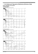
Page 61: ...ts 60 Air Velocity and Temperature Distributions Reference Data 7 Air Velocity and Temperature Distributions Reference Data Model KUE 18HRF32 KUE 24HRF32 Ceiling installation Discharge angle 17 Discharge angle 50 ...

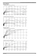
Page 62: ...Indoor Units 61 Air Velocity and Temperature Distributions Reference Data Floor installation Discharge angle 17 Discharge angle 50 ...

Page 63: ...Indoor Units 62 Air Velocity and Temperature Distributions Reference Data Model KUE 36HRF32 Ceiling installation Discharge angle 17 Discharge angle 50 ...

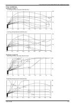
Page 64: ...Indoor Units 63 Air Velocity and Temperature Distributions Reference Data Floor installation Discharge angle 17 Discharge angle 50 ...

Page 65: ...Indoor Units 64 Air Velocity and Temperature Distributions Reference Data Model KUE 48HRF32 KUE 55HRF32 Ceiling installation Discharge angle 17 Discharge angle 50 ...

Page 66: ...Indoor Units 65 Air Velocity and Temperature Distributions Reference Data Floor installation Discharge angle 17 Discharge angle 50 ...

Page 67: ...r Model kBtu h 18 24 36 48 55 POWER Phase 1 phase 3 phase 3 phase Frequency and Voltage 220 240V 50Hz 380 415V 50Hz 380 415V 50Hz POWER WIRING mm2 3 2 5 3 4 0 with auxiliary electric heater 5 2 5 5 4 0 with auxiliary electric heater 5 2 5 5 4 0 with auxiliary electric heater CIRCUIT BREAKER Fuse A 30 20 30 20 30 25 Indoor Outdoor Connecting Wiring Weak Electric Signal mm2 2 0 2 2 0 2 2 0 2 Indoor ...

Page 68: ...Indoor Units 67 Field Wiring 10 Field Wiring KUE 18HRF32 KUE 24HRF32 KUE 36HRF32 KUE 48HRF32 KUE 55HRF32 ...

Page 69: ...y Cassette Type 1 Features 70 2 Dimensions 71 3 Service Space 72 4 Wiring Diagrams 73 5 Air Velocity and Temperature Distributions Reference Data 79 6 Electric Characteristics 80 7 Sound Levels 80 8 Accessories 81 9 The Specification of Power 81 10 Field Wiring 82 ...

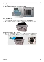
Page 70: ...s very easy for installation and will not damage the decoration The panel size is 647 50 647mm The hooks are designed in the four corners of the body which can save installation space 1 3 Electric control box built in design The E box is simply and safely built inside the indoor unit It s convenient for installation and maintenance Can check the control part easily you only need to open the air re...

Page 71: ... 1 5 0 D i s t r i b u t i o n d u c t 2 1 7 0 P a n e l 5 0 6 4 7 D r a i n h o l e f o r S e r v i c e E p a r t s b o x 4 S c r e w h o l e f o r in s t a ll p a n e 4 in s t a ll h a n g e r 5 4 5 5 7 0 3 2 D r a i n p i p e 6 5 F r e s h a ir i n t a k e 7 5 W i r i n g c o n n e c t i o n p o r t 4 2 6 8 5 7 0 5 2 3 4 4 1 2 6 1 5 7 6 4 7 ...

Page 72: ...Indoor Units 71 Service Space 3 Service Space ...

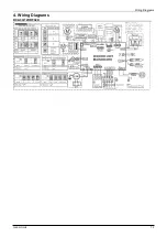
Page 73: ...Indoor Units 72 Wiring Diagrams 4 Wiring Diagrams KCA3U 12HRF32X ...

Page 74: ... the mode what you want when the remote switch off the unit would not respond the demand from remote controller wire controller When the remote switch off but the remote controller wire controller are on CP code would be shown on the display board 6 The voltage of the port is 12V DC design Max current is 5mA B For ALARM terminal port CN33 1 Provide the terminal port to connect ALARM but no voltage...

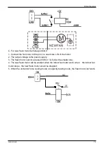
Page 75: ...r 2 The output voltage is the power supply 3 The fresh motor cannot excess 200W or 1A follow the smaller one 4 The new fresh motor will be worked when the indoor fan motor work when the indoor fan motor stops the new fresh motor would be stopped 5 When the unit enter force cooling mode or capacity testing mode the fresh motor isn twork ...

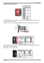
Page 76: ...ding to EEROM setting reserved for special customizing T 2 T E L 0 1 6 T E L 0 1 4 T E L 0 1 2 T E L 0 1 0 T E L 0 8 T E L 0 6 S e t t i n g f a n s p e e d H M M L S u p e r s l o w F a n o f f T E L 0 1 2 T E L 0 1 0 T E L 0 8 T E L 0 6 T E L 0 4 B Micro switch SW2 is for selection of indoor FAN ACTION if room temperature reaches the setpoint and the compressor stops Range OFF in 127s Keep runni...

Page 77: ...ithout difference Slave E Micro switch SW6 is for selection of temperature compensation in heating mode This helps to reduce the real temperature difference between ceiling and floor so that the unit could run properly If the height of installation is lower smaller value could be chosen Range 6oC 4oC 2oC E function reserved for special customizing F Micro switch S1 and dial switch S2 are for addre...

Page 78: ...rom 18K to 55K This ENC1 setting will tell the main program what size the unit is NOTE Usually there is glue on it because the switch position cannot be changed at random unless you want to use this PCB as a spare part to use in another unit Then you have to select the right position to match the size of the unit ...

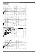
Page 79: ...Indoor Units 78 Air Velocity and Temperature Distributions Reference Data 5 Air Velocity and Temperature Distributions Reference Data T e m p e r a t u r e A irflo w v elo city ...

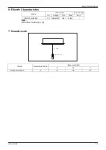
Page 80: ...ric Characteristics Model Indoor Units Power Supply Hz Voltage Min Max MFA KCA3U 12HRF32X 50 220 240V 198V 254V Note MFA Max Fuse Amps A 7 Sound Levels Model Noise Power dB A Noise level dB A H M L KCA3U 12HRF32X 51 41 36 33 1 4 m M i c r o p h o n e ...

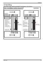
Page 81: ... holder 1 Mounting screw ST2 9 10 C H 2 Remote controller manual 1 Alkaline dry batteries AM4 2 Others Owner s manual 1 Installation manual 1 Installation accessory The product you have might not be provided the following accessories Expansible hook 4 Installation hook 4 Orifice 1 9 The Specification of Power Model kBtu h 12 POWER Phase 1 phase Frequency and Voltage 220 240V 50Hz POWER WIRING mm2 ...

Page 82: ...Outdoor Units Outdoor Units 82 10 Field Wiring KCA3U 12HRF32X ...

Page 83: ...Outdoor Units 83 Outdoor Units Part 3 Outdoor Units 1 Dimensions 84 2 Service Space 86 3 Wiring Diagrams 87 4 Piping Diagrams 95 5 Electric Characteristics 96 6 Operation Limits 97 7 Sound Levels 98 ...

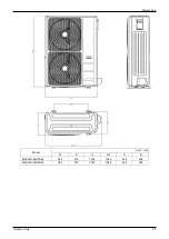
Page 84: ...Units 84 1 Dimensions W 1 W H A B D Model Unit mm W D H W1 A B KOB30 12HFN32X 800 333 554 870 514 340 KOB30U 18HFN32 800 333 554 870 514 340 KOCA30U 24HFN32 845 363 702 914 540 350 KOD30U 36HFN32 946 410 810 1030 673 403 ...

Page 85: ...Dimensions Outdoor Units 85 Model Unit mm W D H W1 A B KOE30U 48HFN32 952 415 1333 1045 634 404 KOE30U 55HFN32 952 415 1333 1045 634 404 ...

Page 86: ...Outdoor Units 86 Service Space 2 Service Space Wall or obstacle More than 30cm Air inlet Air inlet More than 30cm Maintain channel More than 60cm Air outlet More than 200cm More than 60cm ...

Page 87: ...Outdoor Units 87 Wiring Diagrams 3 Wiring Diagrams KOB30 12HFN32X ...

Page 88: ...Outdoor Units 88 Wiring Diagrams KOB30U 18HFN32 ...

Page 89: ...Outdoor Units 89 Wiring Diagrams KOCA30U 24HFN32 ...

Page 90: ...Outdoor Units 90 Wiring Diagrams ...

Page 91: ...Outdoor Units 91 Wiring Diagrams KOD30U 36HFN32 ...

Page 92: ...Outdoor Units 92 Wiring Diagrams ...

Page 93: ...Outdoor Units 93 Wiring Diagrams KOE30U 48HFN32 KOE30U 55HFN32 ...

Page 94: ... m p s e n s o r C O O L I N G H E A T I N G For KOCA30U 24HFN32 there is no accumulator KOD30U 36HFN32 KOE30U 48HFN32 KOE30U 55HFN32 I N D O O R O U T D O O R L I Q U I D S I D E C A P I L I A R Y T U B E E l e c t r o n i c e x p a n s i o n v a l v e 2 W A Y V A L V E T 3 C o n d e n s e r t e m p s e n s o r H E A T E X C H A N G E E V A P O R A T O R H E A T T 2 E v a p o r a t or t e m p s e...

Page 95: ...Supply Hz Voltage Min Max MFA KOB30 12HFN32X 50 220 240V 198V 254V 20 KOB30U 18HFN32 50 220 240V 198V 254V 20 KOCA30U 24HFN32 50 220 240V 198V 254V 20 KOD30U 36HFN32 50 380 415V 342V 440V 20 KOE30U 48HFN32 50 380 415V 342V 440V 25 KOE30U 55HFN32 50 380 415V 342V 440V 25 Notes MFA Max Fuse Amps A ...

Page 96: ...s used beyond the above conditions certain safety protection features may come into operation and cause the unit to operate abnormally 2 The room relative humidity should be less than 80 If the air conditioner operates beyond this figure the surface of the air conditioner may attract condensation Please set the vertical air flow louver to its maximum angle vertically to the floor and set HIGH fan ...

Page 97: ...ne H 7 Sound Levels Outdoor Unit 1 0m Note H 0 5 height of outdoor unit Model Noise Power dB A Noise level dB A KOB30 12HFN32X 61 55 5 KOB30U 18HFN32 65 57 KOCA30U 24HFN32 65 62 KOD30U 36HFN32 66 64 KOE30U 48HFN32 74 66 KOE30U 55HFN32 74 65 ...

Page 98: ...unit installation 102 4 Outdoor unit installation Side Discharge Unit 115 5 Refrigerant pipe installation 116 6 Drainage pipe installation 120 7 Vacuum Drying and Leakage Checking 124 8 Additional refrigerant charge 125 9 Engineering of insulation 126 10 Engineering of electrical wiring 127 11 Test operation 128 ...

Page 99: ...ditional refrigerant charge Vacuum drying and leakage checking Drainage pipe installation and insulation Drainage pipe installation and insulation Refrigerant pipe installation and insulation Refrigerant pipe installation and insulation Outdoor unit installation Indoor unit installation Indoor unit installation location selection Outdoor unit installation location selection ...

Page 100: ... easily support the outdoor unit s weight Locate the outdoor unit as close to indoor unit as possible The piping length and height drop can not exceed the allowable value The place where the noise vibration and outlet air do not disturb the neighbors There is enough room for installation and maintenance The air outlet and the air inlet are not impeded and not face the strong wind It is easy to ins...

Page 101: ...ce for indoor unit Model kBtu h A H 24 36 245 275 48 55 287 317 3 1 2 Bolt pitch 3 1 3 Install the pendant bolt Select the position of installation hooks according to the hook holes positions showed in upper picture Drill four holes of Ø12mm 45 50mm deep at the selected positions on the ceiling Then embed the expansible hooks fittings ...

Page 102: ...a leveling instrument to make sure the levelness of the main body is within 1 Adjust the position to ensure the gaps between the body and the four sides of ceiling are even The body s lower part should sink into the ceiling for 10 12 mm In general L is half of the screw length of the installation hook Locate the air conditioner firmly by wrenching the nuts after having adjusted the body s position...

Page 103: ...ng the panel to the hooks on the mainbody If the panel is with auto lift grille please watch the ropes lifing the grille DO NOT make the ropes enwinded or blocked Tighten the screws under the panel hooks till the panel closely stick on the ceiling to avoid condensate water ...

Page 104: ...ir in grill to the panel then connect the lead terminator of the swing motor and that of the control box with corresponding terminators on the body respectively Install the 4 corner covers back Note The panel shall be installed after the wiring connected ...

Page 105: ...vice space for indoor unit 3 2 2 Bolt pitch Ceiling installation Capacity KBtu h D E 18 24 983 220 36 55 1565 220 Wall mounted installation 3 2 3 Install the pendant bolt Ceiling installation Select the position of installation hooks according to the hook holes positions showed in upper picture ...

Page 106: ...nsible hooks fittings Wall mounted installation Install the tapping screws onto the wall Refer to picture below 3 2 4 Install the main body Ceiling installation The only installation method for the unit with drain pump Remove the side board and the grille Locate the hanging arm on the hanging screw bolt Prepare the mounting bolts on the unit ...

Page 107: ... Put the side panels and grilles back Wall mounted installation Hang the indoor unit by insert the tapping screws into the hanging arms on the main unit The bottom of body can touch with floor or suspended but the body must install vertically ...

Page 108: ...n the ceiling Be sure to mark the areas where ceiling hook holes will be drilled 2 Install and fit pipes and wires after you have finished installing the main body When choosing where to start determine the direction of the pipes to be drawn out Especially in cases where there is a ceiling involved align the refrigerant pipes drain pipes and indoor and outdoor lines with their connection points be...

Page 109: ...nsert suspension bolts into the unit s hanging holes Fasten them using the washers and nuts provided 9 Mount the indoor unit onto the hanging screw bolts with a block Position the indoor unit flat using a level indicator to prevent leaks Note Confirm the minimum drain tilt is 1 100 or more 3 3 4 Duct and accessories installation 1 Install the filter optional according to the size of the air inlet ...

Page 110: ...nsate An internal duct underlayer can be added to reduce noise if the end user requires 3 3 5 Adjust the air inlet direction From rear side to under side Take off ventilation panel and flange cut off the staples at side rail Change the mounting positions of ventilation panel and air return flange When installing the filter mesh fit it into the flange as illustrated in the following figure NOTE All...

Page 111: ...n of installation hooks according to the hook holes positions showed in upper picture Drill four holes of Ø12mm 45 50mm deep at the selected positions on the ceiling Then embed the expansible hooks fittings Face the concave side of the installation hooks toward the expansible hooks Determine the length of the installation hooks from the height of ceiling then cut off the unnecessary part ...

Page 112: ...llation hooks evenly to ensure the balance of the body Use a leveling instrument to make sure the levelness of the main body is within 1 Adjust the position to ensure the gaps between the body and the four sides of ceiling are even The body s lower part should sink into the ceiling for 10 12 mm In general L is half of the screw length of the installation hook Locate the air conditioner firmly by w...

Page 113: ...e panel hooks till the panel closely stick on the ceiling to avoid condensate water Hang the air in grill to the panel then connect the lead terminator of the swing motor and that of the control box with corresponding terminators on the body respectively Note The panel shall be installed after the wiring connected ...

Page 114: ... 410 48 55 634 404 415 4 3 Install the Unit Since the gravity center of the unit is not at its physical center so please be careful when lifting it with a sling Never hold the inlet of the outdoor unit to prevent it from deforming Do not touch the fan with hands or other objects Do not lean it more than 45 and do not lay it sidelong Make concrete foundation according to the specifications of the o...

Page 115: ...Btu h 30m 20m 24 000Btu h 30 000Btu h 50m 25m 36 000Btu h 60 000Btu h 65m 30m 5 2 The procedure of connecting pipes 5 2 1 Choose the pipe size according to the specification table 5 2 2 Confirm the cross way of the pipes 5 2 3 Measure the necessary pipe length 5 2 4 Cut the selected pipe with pipe cutter Make the section flat and smooth L e a n C r u d e B u r r 5 2 5 Insulate the copper pipe Befo...

Page 116: ... pipe and fix it by supporter For horizontal refrigerant pipe the distance between supporters should not be exceed 1m For vertical refrigerant pipe the distance between supporters should not be exceed 1 5m 5 2 13 Connect the pipe to indoor unit and outdoor unit by using two spanners Be sure to use two spanners and proper torque to fasten the nut too large torque will damage the bellmouthing and to...

Page 117: ...th Total pipe length Actual 24K 24K 50m 30K 30K 50m Max branch pipe length 15m L1 L2 Max branch pipe length difference 10m L1 L2 Drop Height Max height difference between indoor unit and outdoor unit 20m H1 Max height difference between indoor units 0 5m H2 5 3 2 Size of joint pipes for indoor unit 5 3 3 Size of joint pipes for outdoor unit 5 3 4 The branching pipe must be installed horizontally e...

Page 118: ...Installation 119 Refrigerant pipe installation ...

Page 119: ...ter flowrate is decided by the capacity of indoor unit Relationship between water flowrate and capacity of indoor unit Capacity x1000Btu Water flowrate l h 12 2 4 18 4 24 6 30 7 36 8 42 10 48 12 60 14 According to the above table to calculate the total water flowrate for the confluence pipe selection For horizontal drainage pipe The following table is for reference PVC pipe Reference value of inne...

Page 120: ...flow or bad flow D r a i n a g e p i p e D r a in a g e p ip e D r a in a g e p ip e D r a i n t e e W a t e r f l o w W a t e r f l o w W a t e r f l o w W a t e r f l o w W a t e r f l o w D r a i n t e e D r a i n t e e W a t e r f l o w W a t e r f l o w W a t e r f l o w W a t e r f l o w B r a n c h p i p e W a t e r f l o w G a s G a s K e e p a c e r t a i n d e g r e e W a t e r f l o w M...

Page 121: ...or installation reference H a n g e r D o w n i n c l i n e p i p e A L e n g t h o f h o r i z o n t a l p i p e 1 5 0 m m B B L i f t h e i g h t t h e p u m p h e a d o f w a t e r p u m p F l e x i b l e p i p e 3 0 0 m m 6 2 8 Blowhole setting For the concentrated drainage pipe system there should design a blowhole at the highest point ofmain pipe to ensure the condensate water discharge smoo...

Page 122: ... at drainage outlet In light of the length of drainage pipe water shall be discharged about 1 minute delayed 2 3 Stop the operation of air conditioner power off the power supply and put the cover of water test hole back to the original place a After stopped the air conditioner 3 minutes check whether there is anything abnormal If drainage pipes have not been distributed properly over back flow wat...

Page 123: ...mmHg after 1 5 hours of drying check whether there is leakage source 4 Leakage test After the vacuum degree reaches 755mmHg stop vacuum drying and keep the pressure for 1 hour If the indicator of vacuum gauge does not go up it is qualified If going up it indicates that there is moisture or leak source 7 3 2 Special vacuum drying The special vacuum drying method shall be adopted when 1 Finding mois...

Page 124: ...quid pipe m Note Refrigerant may only be charged after performed the vacuum drying process Always use gloves and glasses to protect your hands and eyes during the charge work Use electronic scale or fluid infusion apparatus to weight refrigerant to be recharged Be sure to avoid extra refrigerant charged it may cause liquid hammer of the compressor or protections Use supplementing flexible pipe to ...

Page 125: ...ent place the layer of insulation should be thicker accordingly 9 1 4 Installation highlights of insulation construction Gas pipe and liquid pipe shall be insulated separately if the gas pipe and liquid pipe were insulated together it will decrease the performance of air conditioner L iq u id p ip e In s u la tio n m e te ria l G a s p i p e The insulation material at the joint pipe shall be 5 10c...

Page 126: ...ield wiring construction should be finished by qualified electrician Air conditioning equipment should be grounded according to the local electrical regulations Current leakage protection switch should be installed Do not connect the power wire to the terminal of signal wire When power wire is parallel with signal wire put wires to their own wire tube and remain at least 300mm gap According to tab...

Page 127: ... units The gas side and liquid side stop values are both opened The air conditioner is pre heated by turning on the power 11 3 Test operation Set the air conditioner under the mode of COOLING by remote controller and check the following points Indoor unit Whether the switch on the remote controller works well Whether the buttons on the remote controller works well Whether the air flow louver moves...

Page 128: ...Electrical Control System Part 5 Electrical Control System 1 Electrical Control Function 130 2 Troubleshooting 141 3 Controller 175 Electrical Control System 129 ...

Page 129: ...Speed Malfunction For A6 Duct If a fault occurs on the air volume regulator or the regulator enters protection mode it sends the error message CF and an instruction to reduce fan speed to the master The message and the instruction can be inquired with the remote controller or the wired controller Fault and protection information are displayed for one minute After a fault occurs the master unit sho...

Page 130: ...ltage too low 8 Communication fault 9 Parameter fault 10 L3 Current limited 11 L5 Voltage limited 12 Target speed cannot be met during the static pressure calculation process For other models If the indoor fan speed is lower than 300 RPM for 50 seconds or more it shuts off and restarts in 30 seconds If this happens 3 times the unit stops and the LED displays the failure code ...

Page 131: ...tes the same as auto fan in cooling mode with the temperature set at 24 T 1 2 4 H H L 0 7 5 L H L 0 5 L H L 0 2 5 L L 1 3 2 Cooling Mode 1 3 2 1 Outdoor Fan Running Guidelines The outdoor unit can run at different fan speeds depending on T4 Fan speeds vary with the model of air conditioner 12K 18K Fan speed is regulated according to T4 and compressor frequency T 4 a r e a Frequency linkage area A ...

Page 132: ... Setting fan speed T1 Td F Actual fan speed H H H H G A H H B H H H G C M M M M Z D M M M E M M M Z F L L L L D G L L L H L L L D I The auto fan in cooling mode acts as follows T 1 T d H H L 0 7 5 L H L 0 5 L H L 0 2 5 L L 1 3 2 3 Evaporator Low Temperature T2 Protection T2 0 the compressor stops and restarts only when T2 5 0 T2 4 the compressor frequency is limited and decreases to a lower level ...

Page 133: ...l Temperature Protection 12K 18K 24 60K T 3 T 3 1 3 3 Heating Mode 1 3 3 1 Outdoor Fan Running Guidelines 12K 18K Fan speed is regulated according to T4 and compressor frequency T 4 a Frequency linkage area 24 60K T 4 A A B C F r e q u e n c y l i n k a g e a r e A A O f f D e c r e a s e H o l d R e s u m e F r e q u e n c y o f c o m p r e s s o r o p e r a t io n ...

Page 134: ...he compressor stops and the indoor fan motor runs at the minimum speed The anti cold wind is valid The auto fan in heating mode acts as follows T 1 T d L H L 0 2 L H L 0 4 L H L 0 6 L H L 0 6 L H L 0 8 L H 1 3 3 3 Defrosting Control Conditions for defrosting the unit enters the defrosting mode according to the value of T3 and T4 as well as the compressor running time Defrost Stop Conditions If any...

Page 135: ...and cooling the compressor stops for 15 minutes and then selects a mode again according to T1 Ts If the temperature is modified the machine selects a running function 1 3 5 Dehumidifier Mode The indoor fan speed is fixed at breeze and can t be changed All protections are activated and operate the same as they do in cooling mode 1 3 6 Timer Function 1 3 6 1 The timing range is 24 hours 1 3 6 2 Time...

Page 136: ...ically The module automatically stores the current settings not including the Swing setting and in the case of a sudden power failure will restore those setting automatically within 3 minutes after power returns 1 3 9 Drain Pump Control For Duct and Cassette Use the water level switch to control drain pump The system checks the water level every 5 seconds When the A C operates in cooling including...

Page 137: ...n 99 the digital display shows single and double digits For example if the digital display shows 0 5 the compressor discharge temperature is 105 If the digital display shows 1 6 the compressor discharge temperature is 116 10 AD value of current The display value is a hexidecimal number 11 AD value of voltage 12 Indoor unit running mode code Off 0 Fan only 1 Cooling 2 Heating 3 Forced cooling 4 Dry...

Page 138: ...t capacity demand code 24 Reserved 25 Indoor room temperature of 1 indoor unit If the temperature is lower than 9 the digital display shows 9 If the temperature is higher than 70 the digital display shows 70 If the capacity demand is 0 the digital display shows 0 If the indoor unit is not connected the digital display shows 26 Indoor room temperature of 2 indoor unit If the temperature is lower th...

Page 139: ...ication malfunction between indoor and outdoor units 16 Communication error between outdoor main chip and compressor driven chip IR341 17 AC power input voltage protection 18 Top temperature protection of compressor 19 Outdoor EE Malfunction 20 Fan speed malfunction 21 Temperature sensor open or short circuit 22 Overcurrent protection 23 IMP overcurrent protection 24 Compressor lack of phase 25 Co...

Page 140: ...nation on indoor display board A6 Duct Timer indicator Operation lamp Temporary button PRE DEF indicator cooling and heating type or fan only indicator cooling only type Alarm indicator Infrared signal receiver Display digital tube MANUAL OPERATION TIMER DEF FAN ALARM 2 1 3 Display board of Ceiling floor indoor unit 2 1 4 Display board of compact four way cassette ...

Page 141: ...open or short circuit F1 O 2 T3 temperature sensor open or short circuit F2 O 3 T5 temperature sensor open or short circuit F3 O 4 Outdoor EEPROM malfunction for some units F4 O 5 Outdoor fan speed malfunction F5 O 6 T2B temperature open or short circuit for free match indoor units F6 O 7 Communication error between auto lifting panel and slim cassette F7 O 8 Auto lifting panel is faulty for slim ...

Page 142: ...unction P0 IPM module protection P1 DC voltage too high too low protection P3 Ultra low ambient temperature protection P4 Compressor rotor position protection J0 Evaporator high temperature protection J1 Condenser high temperature protection J2 High discharge temperature protection J3 PFC module protection J4 Communication error between outdoor main chip and compressor driven chip J5 High pressure...

Page 143: ... o ou u ut ttd d do o oo o or r r m m ma a aiin n n b b bo o oa a ar r rd d d d d diis s sp p plla a ay y y a a an n n e e er r rr r ro o or r r c c co o od d de e e a a a f ffe e ew w w m m miin n nu u ut tte e es s s lla a at tte e er r r C C Ch h he e ec c ck k k c c co o on n nn n ne e ec c ct ttiio o on n ns s s b b be e et ttw w we e ee e en n n t tte e em m mp p pe e er r ra a at ttu u ur r...

Page 144: ... s t tth h he e e m m ma a allf ffu u un n nc c ct ttiio o on n n s s st ttiill ll n n no o ot tt r r re e es s so o ollv v ve e ed d d Yes I IIs s s t tth h he e e w w wa a at tte e er r r lle e ev v ve e ell s s sw w wiit ttc c ch h h iin n ns s se e er r rt tte e ed d d p p pr r ro o op p pe e er r rlly y y P P Po o ow w we e er r r o o of fff ff t tth h he e en n n r r re e es s st tta a ar r ...

Page 145: ... of ff t tth h he e e p p pr r ro o ob b blle e em m m a a an n nd d d r r re e es s so o ollv v ve e e iit tt F F Fo o or r r e e ex x xa a am m mp p plle e e tth he effa an nm ma ay y b be eb bllo oc ck ke ed do orrtth he es sc crre ew ws s w wh hiic ch hffiix xtth he effa an niin np plla ac ce e a arre etto oo ottiig gh htt S S Sh h hu u ut tt o o of fff ff t tth h he e e p p po o ow w we e er ...

Page 146: ...Vcc 13 5 16 5V 5 Yellow Vsp 0 6 5V 6 Blue FG 13 5 16 5V 2 Indoor or outdoor DC Fan Motor control chip is in PCB Release the UVW connector Measure the resistance of U V U W and V W If the resistances are not equal to each other the fan motor may be experiencing problems and need to be replaced Otherwise the PCB must has problems and need to be replaced ...

Page 147: ...first 8 minutes after the compressor starts up if T2 Tcool 2 is not maintained for 4 seconds and compressor running frequency is not higher than 50Hz for 3 minutes Potential causes T2 sensor error Indoor PCB error Refrigerant system error such as leakage or blockages Yes Yes No Yes Yes Shut off the power supply and turn it on 2 minutes later Is it still displaying the error code Is there cool air ...

Page 148: ...Communication malfunction between indoor and outdoor units The same as E1 in outdoor Replace outdoor main PCB Check the connection between temperature sensor and PCB Is it properly wired Measure the resistance value of the sensor Is it within acceptable parameters Replace the sensor Ensure proper connection ...

Page 149: ...wn n n n n no o or r rm m ma a all lly y y Yes U U Up p p d d do o ow w wn n n p p pa a an n ne e ell iis s s d d de e ef ffe e ec c ct ttiiv v ve e e No C C Ch h he e ec c ck k k t tth h he e e w w wiir r riin n ng g g o o of ff lle e ef fft tt a a an n nd d d r r riig g gh h ht tt s s se e en n ns s so o or r rs s s A A Ar r re e e t tth h he e ey y y c c co o or r rr r re e ec c ct ttlly y y w ...

Page 150: ... e o o u u t t d d o o o o r r u u n n i it t s se e p p a a r r a a t t e e l l y y T T h h e e o o n n e e t t h h a at t d d i is s p p l la a y y s sa a n n E E 1 1 eerrr roor rccooddeeiissddeeffee ccttiivvee E8D Diis sp plla ay ye ed d C Ch he ec ck ktth he ed diia alls sw wiittc ch hs se ettttiin ng gs so off m ma asstte erru un niitta an nd ds slla av ve eu un niitt A Arre etth he ey y cco ...

Page 151: ... c c ch h hiip p p E E EE E EP P PR R RO O OM M M m m ma a allf ffu u un n nc c ct ttiio o on n n P P Po o ow w we e er r r o o of fff ff t tth h he e en n n r r re e es s st tta a ar r rt tt t tth h he e e u u un n niit tt 2 2 2 m m miin n nu u ut tte e es s s lla a at tte e er r r D D Do o oe e es s s t tth h he e e m m ma a allf ffu u un n nc c ct ttiio o on n n s s st ttiill ll r r re e em m m...

Page 152: ... ct tte e ed d d p p pr r ro o op p pe e er r rlly y y Yes No Yes R R Re e ec c co o on n nn n ne e ec c ct tt a a an n nd d d r r re e et ttr r ry y y I IIs s s t tth h he e e e e er r rr r ro o or r r s s st ttiill ll d d diis s sp p plla a ay y ye e ed d d Yes R R Re e ep p plla a ac c ce e e t tth h he e e o o ou u ut ttd d do o oo o or r r m m ma a aiin n n P P PC C CB B B I IIs s s t tth h h...

Page 153: ...f fff ff t tth h he e en n n r r re e es s st tta a ar r rt tt t tth h he e e u u un n niit tt 2 2 2 m m miin n nu u ut tte e es s s lla a at tte e er r r D D Do o oe e es s s a a a p p pr r ro o ob b blle e em m m s s st ttiill ll e e ex x xiis s st tt R R Re e ep p plla a ac c ce e e t tth h he e e o o ou u ut ttd d do o oo o or r r m m ma a aiin n n P P PC C CB B B ...

Page 154: ...r r w w wiir r riin n ng g g c c co o on n nn n ne e ec c ct ttiio o on n n H H Ha a as s s t tth h he e e p p pr r ro o ob b blle e em m m b b be e ee e en n n r r re e es s so o ollv v ve e ed d d R R Re e ep p plla a ac c ce e e t tth h he e e r r re e ea a ac c ct tto o or r r P P Po o ow w we e er r r o o of fff ff t tth h he e en n n r r re e es s st tta a ar r rt tt t tth h he e e u u un n ...

Page 155: ... o ob b blle e em m m s s st ttiill ll e e ex x xiis s st tt R R Re e ep p plla a ac c ce e e t tth h he e e iin n nd d do o oo o or r r m m ma a aiin n n P P PC C CB B B iis s s t tth h he e e e e er r rr r ro o or r r r r re e es s so o ollv v ve e ed d d I IIs s s t tth h he e er r re e e a a an n ny y y iin n nt tte e er r rf ffe e er r re e en n nc c ce e e s s su u uc c ch h h a a as s s t t...

Page 156: ... System 157 2 4 4 5 F0 Malfunction Malfunction conditions If the outdoor current exceeds the current limit value the LED displays a failure code Possible causes Wiring mistakes Faulty bridge rectifier System blockages Faulty outdoor PCB ...

Page 157: ...r rre e ea a ac c ctto o or rr a a an n n d d d iin n nd d du u uc c ctta a an n nc c ce e e ffu u un n nc c cttiio o on n niin n ng g g n n no o or rrm m ma a alllly y y No Yes IIs s s tth h he e e h h he e ea a att e e ex x x c c ch h h a a a n n ng g g e e er rr d d diir rrtty y y Yes No R R Re e ep p plla a ac c ce e e o o ou u uttd d do o oo o or rr m m ma a aiin n n b b bo o oa a ar rrd d d ...

Page 158: ...rr T T T5 5 5 iis s sm m ma a allf ffu u un n nc c ct ttiio o on n niin n ng g g 2 4 4 6 F1 F2 F3 Malfunction F1 IIs s s t tth h he e e w w wiir rriin n ng g g o o of ff t tth h he e e c c co o on n nd d de e en n ns s se e er rr t tte e em m mp p p s s se e en n ns s so o or r r T T T3 3 3 n n no o ot tt c c co o on n nn n ne e ec c ct tte e ed d d p p pr r ro o op p pe e er r rlly y y Yes No Yes...

Page 159: ... in indoor unit R R Re e ep p plla a ac c ce e e t tth h he e e o o ou u ut ttd d do o oo o or r r m m ma a aiin n n P P PC C CB B B F F F4 4 4 D D Diis s sp p plla a ay y y O O Ou u ut ttd d do o oo o or r r E E EE E EP P PR R RO O OM M M m m ma a allf ffu u un n nc c ct ttiio o on n n P P Po o ow w we e er r r o o of fff ff t tth h he e en n n r r re e es s st tta a ar r rt tt t tth h he e e u u...

Page 160: ...is not normal the LED displays P0 and the unit turns off Possible causes Wiring mistakes Faulty IPM board Faulty outdoor fan assemby Compressor malfunction Faulty outdoor PCB First test the resistance between every two ports of U V the W of the IPM and P N If any of the results is 0 or close to 0 the IPM is defective If not follow the following procedure ...

Page 161: ...o o o tt b b b e e e e e e n n n d d d o o o n n n e e e a a allr rre e ea a ad d dy y y R R Re e effe e er rr tto o o tth h he e e s s so o ollu u uttiio o on n n ffo o or rr tth h he e em m ma a allffu u un n nc c cttiio o on n n o o off tth h he e e ffa a an n n s s s p p p e e e e e e d d d b b be e eiin n ng g g o o ou u utt o o off c c co o on n nttr rro o oll F F Fiin n nd d d tth h he e e ...

Page 162: ...ng the specified voltage detection circuit Supposed causes Abnormal power supply Wiring mistake Faulty bridge rectifier Faulty IPM board No Yes Yes No Yes Yes No P P P1 1 1 d d diis s sp p plla a ay y y R R Re e ec c co o on n nn n ne e ec c ct tt iit tt w w we e ell ll C C Ch h he e ec c ck k k w w wh h he e et tth h he e er r r b b br r riid d dg g ge e e r r re e ec c ct ttiif ffiie e er r r ii...

Page 163: ... oc c ck k ke e ed d d Yes No IIs s s t tth h he e e iin n nd d do o oo o or rr f ffa a an n n r rru u un n nn n niin n ng g g n n no o or r rm m ma a al l llly y y No Yes A A Ar rre e e t tth h he e e h h he e ea a at tt e e ex x xc c ch h ha a an n ng g ge e er rr a a an n nd d d f ffiillt tte e er r r d d diir r rt tty y y Yes No Yes R R Re e ep p plla a ac c ce e e t tth h he e e iin n nd d do...

Page 164: ... g No p p pr rro o o p p pe e e r rrlly y y Yes IIs s s tth h he e e h h he e ea a att e e ex x x c c c h h ha a an n ng g ge e er r r d d diir r rtty y y Yes Yes No R R Re e ep p plla a ac c ce e e o o ou u uttd d do o oo o or r r m m ma a aiin n n b b bo o oa a ar r rd d d H H Ha a as s s tth h he e e p p pr r ro o ob b blle e em m m b b be e ee e en n n r r re e es s so o ollv v ve e ed d d No ...

Page 165: ...h he e e A A Ap p pp p pe e en n nd d diix x x 2 2 2 D D Do o oe e es s s a a a p p pr r ro o ob b blle e em m m s s st ttiill e e ex x xiis s st tt No T T Te e em m mp p pe e er r ra a at ttu u ur r re e e p p pr r ro o ot tte e ec c ct tti iio o on n n o o of ff c c co o om m mp p pr r re e es s ss s so o or r r d d di iis s sc c ch h ha a ar r rg g ge e e R R Re e ep p plla a ac c ce e e t tth ...

Page 166: ...n n no o ott Yes No M M Me e ea a as s su u ur r re e e w w wh h he e et tth h he e er r r t tth h he e e v v vo o ollt tta a ag g ge e e b b be e et ttw w we e ee e en n n P P P a a an n nd d d N N N iis s s n n no o or r rm m ma a all r r re e ef ffe e er r r t tto o o t tth h he e e A A Ap p pp p pe e en n nd d diix x x 3 3 3 Yes R R Re e ep p plla a ac c ce e e t tth h he e e o o ou u ut ttd d...

Page 167: ...iil l llld d diis s sp p plla a ay y ye e ed d d No No R R Re e ep p plla a ac c ce e e C C Co o om m mp p pr r re e es s ss s so o or r r d d dr r riiv v ve e en n n C C Ch h hiip p p I IIs s s t tth h he e e s s sy y ys s st tte e em m m r r ru u un n nn n niin n ng g g n n no o or r rm m ma a al l llly y y Yes No R R Re e ep p plla a ac c ce e e o o ou u ut ttd d do o oo o or r r m m ma a aiin ...

Page 168: ...e e o o ou u uttd d do o oo o or r r m m ma a aiin n n b b bo o oa a ar r rd d d IIs s s tth h he e e p p pr r ro o ob b blle e em m m r r re e es s so o ollv v ve e ed d d No C C Ch h he e ec c c k k k w w wh h he e etth h he e er r r tth h he e e r r re e effr r riig g ge e er r ra a an n ntt s s sy y ys s stte e em m m iis s s ffu u un n nc c cttiio o on n niin n ng g g p p pr r ro o op p pe e ...

Page 169: ... p p p r r ro o o t tt e e e c c ct tt o o o r r r I I If ff t tt h h he e e p p pr r ro o o t tt e e e c c ct tt o o o r r r iis s s n n no o o r r r m m ma a a llt tt h h he e e v v va a allu u ue e e iis s s o o o D D Do o o e e e s s s a a a p p pr r ro o o b b blle e e m m m s s st ttiill ll e e ex x xiis s st tt No Yes I IIs s s t tth h he e e o o ou u ut ttd d do o oo o or r r a a am m mb b...

Page 170: ...detection circuit Supposed causes Abnormal power supply Wiring mistake Faulty bridge rectifier Faulty IPM board No Yes Yes No Yes Yes No J J J8 8 8 d d diis s sp p plla a ay y y R R Re e ec c co o on n nn n ne e ec c ct tt iit tt w w we e ell ll C C Ch h he e ec c ck k k w w wh h he e et tth h he e er r r b b br r riid d dg g ge e e r r re e ec c ct ttiif ffiie e er r r iis s s n n no o or r rm m ...

Page 171: ... 6 13059 76 1 34105 116 0 40060 3 41 5878 37 5 87359 77 1 29078 117 0 38991 2 39 8239 38 5 62961 78 1 25423 118 0 37956 1 37 1988 39 5 39689 79 1 21330 119 0 36954 0 35 2024 40 5 17519 80 1 17393 120 0 35982 1 33 3269 41 4 96392 81 1 13604 121 0 35042 2 31 5635 42 4 76253 82 1 09958 122 0 3413 3 29 9058 43 4 57050 83 1 06448 123 0 33246 4 28 3459 44 4 38736 84 1 03069 124 0 32390 5 26 8778 45 4 21...

Page 172: ...4 2 489 5 234 9 35 35 78 75 8 084 115 2 422 4 222 8 36 34 32 76 7 82 116 2 357 3 211 4 37 32 94 77 7 566 117 2 294 2 200 7 38 31 62 78 7 321 118 2 233 1 190 5 39 30 36 79 7 086 119 2 174 0 180 9 40 29 15 80 6 859 120 2 117 1 171 9 41 28 81 6 641 121 2 061 2 163 3 42 26 9 82 6 43 122 2 007 3 155 2 43 25 86 83 6 228 123 1 955 4 147 6 44 24 85 84 6 033 124 1 905 5 140 4 45 23 89 85 5 844 125 1 856 6 ...

Page 173: ...ng Appendix 3 Normal voltage of P and N 208 240V 1 phase 3 phase 380 415V 3 phase In standby around 310VDC around 530VDC In operation With passive PFC module With partial active PFC module With fully active PFC module 200VDC 310VDC 370VDC 450VDC ...

Page 174: ...Wireless Remote Controller 3 1 1RG51Q1 BGE General Function for wireless remote controller Model RG51Q1 BGE Rated voltage 3 0V 2pieces of LR03 7 batteries Min voltage for sending signal of CPU 2 4V Effective receiving distance 8m 11m Operation condition 5 60 ...

Page 175: ... 8 FAN SPEED Fan speed will be selected in following sequence once pressing this button 9 TIME ON For time ON setting Once pressing this button the time will increase by 0 5 hour When the set time exceeds 10 hours pressing the button will increase the time by 1 hour Adjusting the figure to 0 00 will cancel time ON setting 10 ECO Activate or turn off economic operation mode It is suggested to turn ...

Page 176: ...Lock Reset 1 Adjust Decrease the set temperature Keeping pressing will decrease the temp with 1 per 0 5s 2 Adjust Increase the set temperature Keeping pressing will increase the temp with 1 per 0 5s 3 MODE Once pressing running mode will be selected in the following sequence NOTE No heating mode for cool only type unit 4 VERT SWING Used to stop or start horizontal louver movement The louver will s...

Page 177: ...This function is available on COOL HEAT or AUTO mode only NOTE While the unit is running under Energy saving mode it would be cancelled if press MODE FAN SPEED or ON OFF button 11 TIME OFF For time OFF setting Once pressing this button the time will increase by 0 5 hour When the set time exceeds 10 hours pressing the button will increase the time by 1 hour Adjust the figure to 0 00 will cancel tim...

Page 178: ...if push this button 5 RESET inner located Once the recessed RESET button is pressed all of the current settings will be cancelled and the controller will return to the initial settings 6 AIR DIRECTION P Press this button to change the swing angle of the louver The swing angle of the louver is 6o for each press When the louver swing at a certain angle which would affect the cooling and heating effe...

Page 179: ...t time exceeds 10 hours pressing the button will increase the time by 1 hour Adjust the figure to 0 00 will cancel time ON setting 13 LOCK inner located Push this button to lock in all the current settings and the remote controller will not accept any operation except that of the LOCK Use the LOCK mode when you want to prevent settings from being changed accidentally Press the LOCK button again to...

Page 180: ...er each press If cancel this function just set it to 0 0 4 Follow me button When under cool heat and auto mode press this button follow me function is active Press again this function is ineffective 5 Electrical heater button If press this button in heat mode electrical heater function become ineffective 6 Reset button hidden Use a 1mm stick to press in the little hole then the current setting is ...

Page 181: ...roller 1 Operation mode indication When press MODE button the following mode can be selected in circle Auto Cool Dry Heat Fan only Auto Auto Cool Dry Heat Fan only Auto For cooling only model heat mode is skipped 2 Timer When adjust setting on time or only on time is set the ON is lighted When adjust setting off time or only off time is set the OFF is lighted If on and off timer are both set the O...

Page 182: ...tallation Notice When the air conditioner needs the constant frequency wire controller be sure adding a wire joint with 5 terminal named A B C D E in indoor unit and fixing an infrared emitter whose anode and cathode connecting with A and B near the receiver in the indoor unit switch board then connecting the terminal 5v GND Run in the switch board to C D E respectively NOTE The connecting wire sh...

Page 183: ...Controller Electrical Control System 184 ...

Page 184: ...Controller Electrical Control System 185 ...

Page 185: ...Controller Electrical Control System 186 ...

Page 186: ...Controller Electrical Control System 190 ...

Reviews: