29
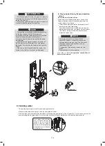
Be careful not to deform the unit’s piping by
using excessive force when connecting the
piping. Deforming the piping can cause the unit
to malfunction.
CAUTION
Selecting the additional expansion vessel
If the expansion vessel of the unit is too small for the
installation, an additional expansion vessel is needed.
calculate the pre-pressure of the expansion vessel:
Pg(bar)=(H(m)/10+0.3) bar
the expansion vessel equipped in the unit should
adjust the pre- pressure also.
calculate the volume needed of the additional expan-
sion vessel:
V1=0.0693*Vwater/(2.5-Pg)-V0
Vwater is volume of water in the system, V0 is volume
of expansion vessel which the unit is equipped(8L).
9.4.3 Water circuit connection
Water connections must be made correctly in
accordance with labels on the outdoor unit, with respect
to the water inlet and water outlet.
Use clean pipes only.
Hold the pipe end downwards when removing burrs.
Cover the pipe end when inserting it through a wall to
prevent dust and dirt entering.
Use a good thread sealant for sealing the connec-
tions. The sealing must be able to withstand the
pressures and temperatures of the system.
When using non-copper metallic piping, be sure to
insulate two kind of materials from each other to
prevent galvanic corrosion.
If air, moisture or dust gets in the water circuit, problems
may occur. Therefore, always take into account the
following when connecting the water circuit:
For copper is a soft material,
use appropriate tools for
connecting the water circuit.
Inappropriate tools will cause
damage to the pipes.
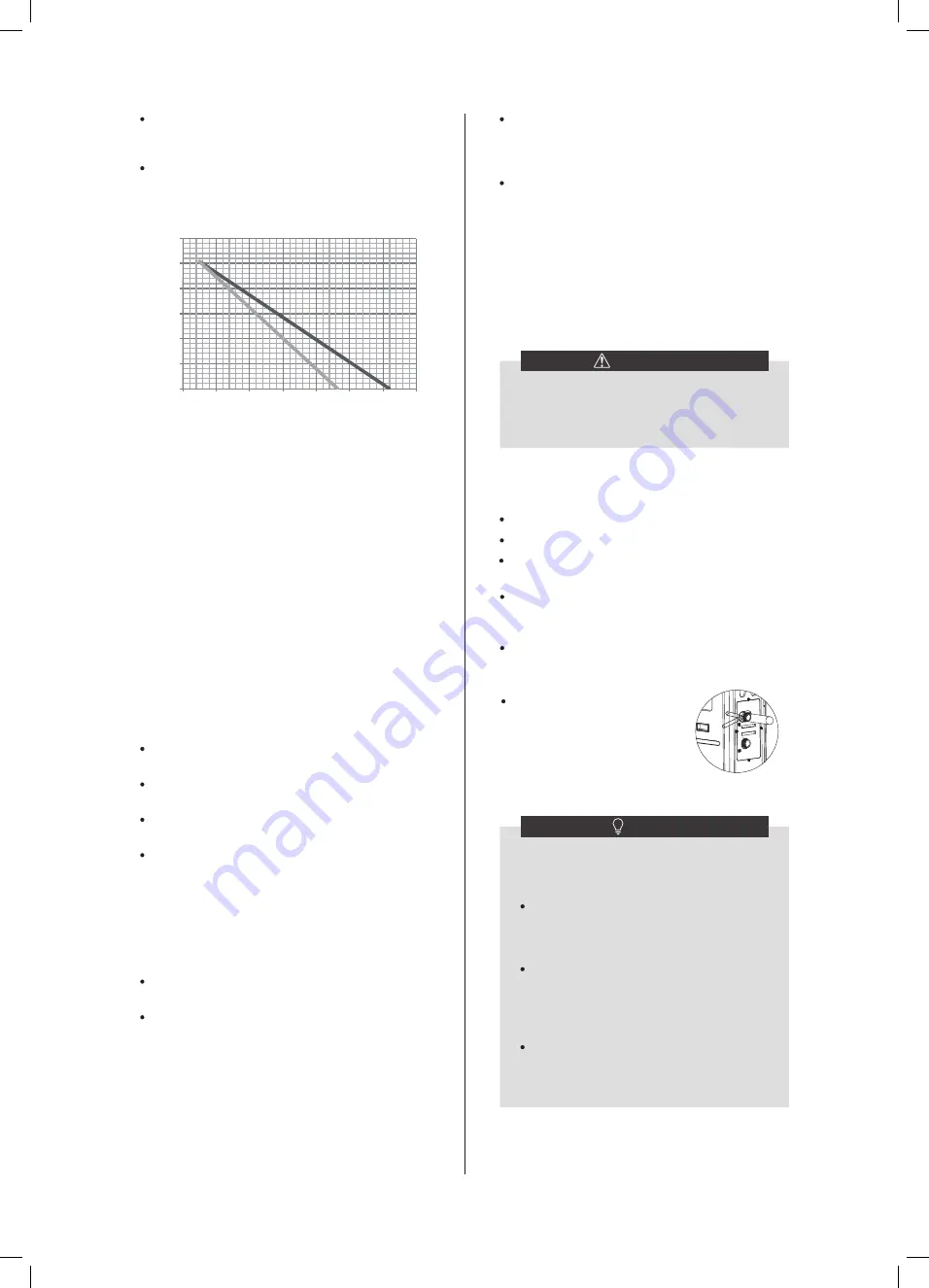
Pre-pressure = pre-pressure of the expansion vessel
Maximum water volume = maximum water volume in the
system
A1 System without glycol
A2 System without 25% propylene glycol
Example 1
:
The unit is installed 5m below the highest point in the
water circuit. The total water volume in the water circuit is
100 L. In this example, no action or adjustment is
required.
Example 2
:
The unit is installed at the highest point in the water
circuit. The total water volume in the water circuit is 250
L.
Result:
Since 250 L is more than 230 L, the pre-pressure
must be decreased (see table above).
The required pre-pressure is: Pg(bar) =
(H(m)/10+0.3) bar = (0/10+0.3) bar = 0.3 bar
The corresponding maximum water volume can be
read from the graph: approximately 310L.
Since the total water volume (250L) is below the
maximum water volume (310L), the expansion vessel
suffices for the installation.
Setting the pre-pressure of the expansion vessel
When it is required to change the default pre-pressure of
the expansion vessel (1.0 bar), following guidelines:
Use only dry nitrogen to set the expansion vessel
pre-pressure.
Inappropriate setting of the expansion vessel
pre-pressure will lead to malfunctioning of the
system. Pre-pressure should only be adjusted by a
licensed installer.
Determine the calculated pre-pressure (Pg) for the
corresponding maximum water volume using the
graph below.
Check that the total water volume in the entire water
circuit is lower than this value. If this is not the case,
the expansion vessel inside the unit is too small for
the installation.
NOTE
Never use Zn-coated parts in the water
circuit. Excessive corrosion of these parts
may occur as copper piping is used in the
unit's internal water circuit.
When using a 3-way valve in the water circuit.
Preferably choose a ball type 3-way valve to
guarantee full separation between the
domestic hot water and floor heating water
circuit.
When using a 3-way valve or a 2-way valve in
the water circuit. The recommended
maximum changeover time of the valve
should be less than 60 seconds.
The unit is only to be used in a closed water
system. Application in an open water circuit can
lead to excessive corrosion of the water piping:
0.3
0.8
1.3
1.8
2.3
2.8
3.3
0
50
100
150
200
250
300
350
Pre-
pr
es
su
re
[b
ar
]
Max. water volume [L]
A1
A2
30
9.4.4 Water circuit anti-freeze protection
Ice formation can cause damage to the hydraulic system.
As the outdoor unit may be exposed to sub-zero
temperatures, care must be taken to prevent freezing of
the system.
All internal hydronic parts are insulated to reduce heat
loss. Insulation must also be added to the field piping.
The software contains special functions using the heat
pump to protect the entire system against freezing. When
the temperature of the water flow in the system drops to
a certain value, the unit will heat the water, either using
the heat pump, the electric heating tap, or the backup
heater. The freeze protection function will turn off only
when the temperature increases to a certain value.
In event of a power failure, the above features would not
protect the unit from freezing.
Do one of the following to protect the water circuit
against freezing:
▪
Add glycol to the water. Glycol lowers the freezing
point of the water.
Install freeze protection valves. Freeze protection
valves drain the water from the system before it can
freeze.
▪
1. Freeze protection by glycol
About freeze protection by glycol
Adding glycol to the water lowers the freezing point of water.
Types of glycol
The types of glycol that can be used depend on whether the
system contains a domestic hot water tank:
If the system contains a domestic hot water tank, then only
use propylene glycol*;
If the system does NOT contain a domestic hot water tank,
then you can use either propylene glycol* or ethylene glycol;
*Propylene glycol, including the necessary inhibitors, classified as
Category III according to EN1717.
Required concentration of glycol
The required concentration of glycol depends on the lowest
expected outdoor temperature, and on whether you want to
protect the system from bursting or from freezing. To prevent
the system from freezing, more glycol is required.
Add glycol according to the table below
:
If you add glycol to the water, do NOT install
freeze protection valves. Possible conse-
quence: Glycol leaking out of the freeze
protection valves.
WARNING
Ethylene glycol is toxic.
WARNING
Due to the presence of glycol, corrosion of the system is
possible. Uninhibited glycol will turn acidic under the
influence of oxygen. This process is accelerated by the
presence of copper and high temperatures. The acidic
uninhibited glycol attacks metal surfaces and forms
galvanic corrosion cells that cause severe damage to the
system. Therefore it is important that:
▪ the water treatment is correctly executed by a qualified
water specialist,
▪ a glycol with corrosion inhibitors is selected to counteract
acids formed by the oxidation of glycols,
▪ no automotive glycol is used because their corrosion
inhibitors have a limited lifetime and contain silicates which
can foul or plug the system,
▪ galvanized pipes are NOT used in glycol systems since
the presence may lead to the precipitation of certain
components in the glycol's corrosion inhibitor.
Glycol absorbs water from its environment. Therefore do
NOT add glycol that has been exposed to air. Leaving the
cap off the glycol container causes the concentration of
water to increase. The glycol concentration is then lower
than assumed. As a result, the hydraulic components
might freeze up after all. Take preventive actions to ensure
a minimal exposure of the glycol to air.
NOTE
NOTE
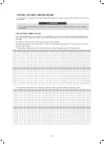
Ethylene Glycol
Quality of
glycol
0%
10%
20%
30%
1.000
0.984
0.973
0.965
1.000
0.998
0.995
0.992
1.000
1.118
1.268
1.482
1.000
1.019
1.051
1.092
0
℃
-5
℃
-15
℃
-25
℃
Minimum
outdoor
temperature
Cooling capacity
modification
Power
modification
Water
resistance
Water flow
modification
Modification coefficient
Propylene Glycol
Quality of
glycol
0%
10%
20%
30%
1.000
0.976
0.961
0.948
1.000
0.996
0.992
0.988
1.000
1.071
1.189
1.380
1.000
1.000
1.016
1.034
0
℃
-4
℃
-12
℃
-20
℃
Minimum
outdoor
temperature
Cooling capacity
modification
Power
modification
Water
resistance
Water flow
modification
Modification coefficient
113
112
Summary of Contents for MONO KHC-22RX3
Page 1: ...INSTRUKCJA INSTALACYJNA INSTALATIONMANUAL POMPA CIEPŁA MONO MONO TYPE HEAT PUMP PL EN ...
Page 2: ......
Page 79: ...79 ...
Page 80: ......
Page 157: ...NOTE 157 ...
Page 158: ...NOTE ...
Page 159: ...16125300002403 V C ...
Page 160: ...kaisai com ...


