41
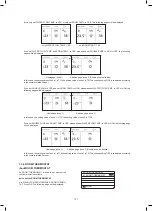
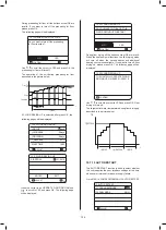
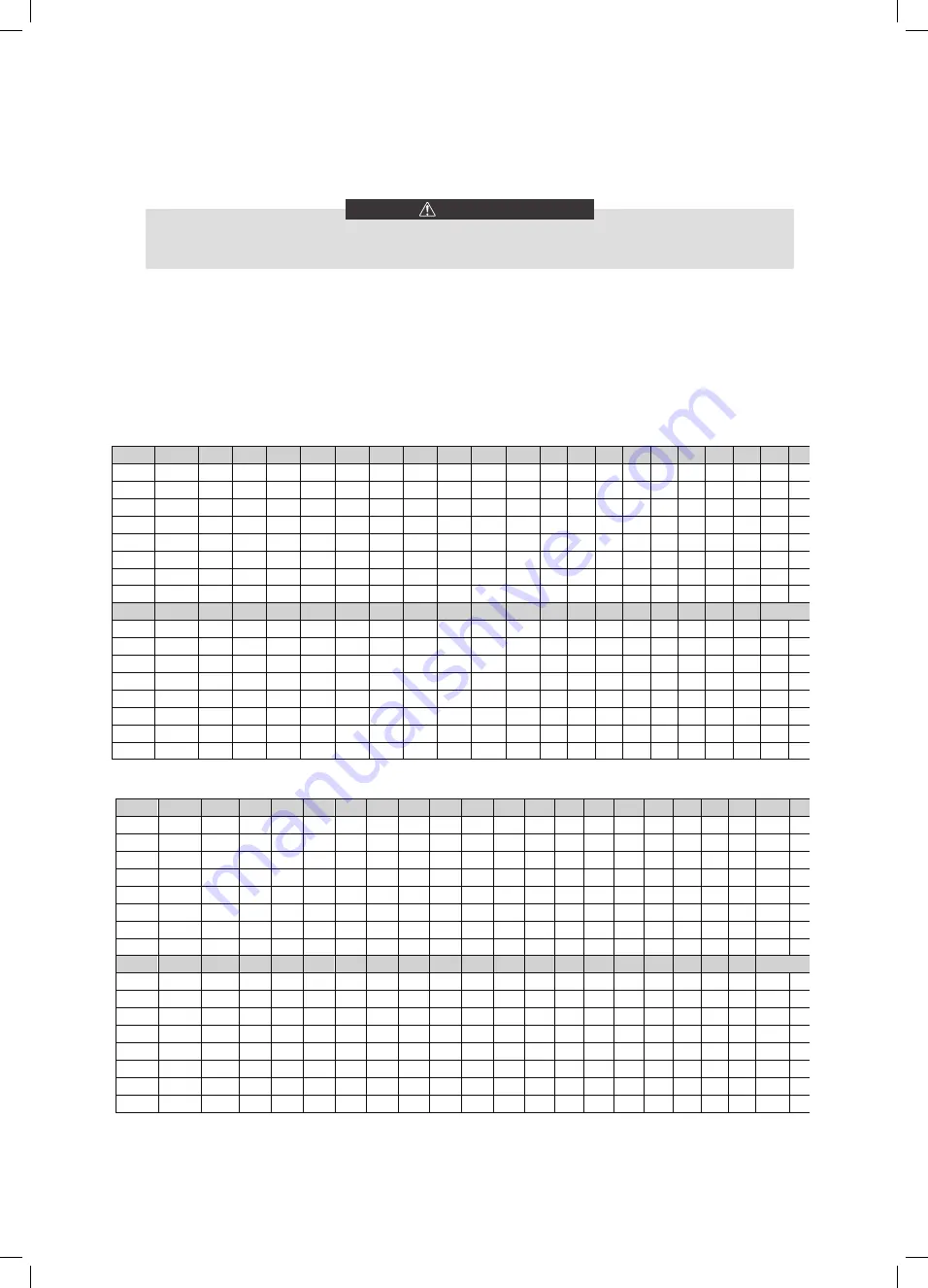
1.The environment temperature curves of the low temperature setting for heating mode and ECO heating mode
2.The environment temperature curves of the high temperature setting for heating mode and ECO heating mode
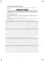
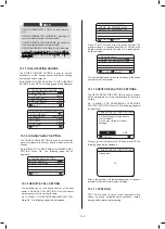
10 START-UP AND CONFIGURATION
The unit should be configured by the installer to match the installation environment (outdoor climate, installed options, etc.) and
user expertise.
It is important that all information in this chapter is read sequentially by the installer and that the system is configured
as applicable.
CAUTION
10.1 Climate related curves
The Climate related curves can be selected in the user interface. Once the curve is selected, the target outlet temperature. In
each mode, user can select one curve from curves in the user interface(curve can’t be selected if dual room thermostat function
is enabled.
It’s possible to select curves even dual room thermostat function is enabled.
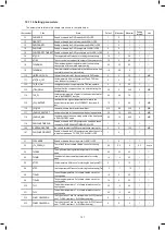
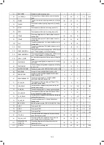
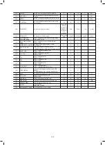
The relationship between outdoor temperature (T4/°C) and the target water temperature(T1S/°C) is described in the table and
picture in the next page. )
T4
≤
-20
-19
-18
-17
-16
-15
-14
-13
-12
-11
-10
-9
-8
-7
-6
-5
-4
-3
-2
-1
0
1-T1S
38
38
38
38
38
37
37
37
37
37
37
36
36
36
36
36
36
35
35
35
35
2-T1S
37
37
37
37
37
36
36
36
36
36
36
35 35 35 35 35 35 34 34 34 34
3-T1S
36
36
36
35
35
35
35
35
35
34
34
34 34 34 34 33 33 33 33 33 33
4-T1S
35
35
35
34
34
34
34
34
34
33
33
33 33 33 33 32 32 32 32 32 32
5-T1S
34
34
34
33
33
33
33
33
33
32
32
32 32 32 32 31 31 31 31 31 31
6-T1S
32
32
32
32
31
31
31
31
31
31
31
31 30 30 30 30 30 30 30 30 29
7-T1S
31
31
31
31
30
30
30
30
30
30
30
30 29 29 29 29 29 29 29 29 28
8-T1S
29
29
29
29
28
28
28
28
28
28
28
28 27 27 27 27 27 27 27 27 26
T4
1
2
3
4
5
6
7
8
9
10
11
12
13
14
15
16
17
18
19
≥
20
1-T1S
35
35
34
34
34
34
34
34
33
33
33
33
33
33
32
32
32
32
32
32
32
2-T1S
34
34
33
33
33
33
33
33
32
32
32
32 32 32 31 31 31 31 31 31 31
3-T1S
32
32
32
32
32
32
31
31
31
31
31
31 30 30 30 30 30 30 29 29 29
4-T1S
31
31
31
31
31
31
30
30
30
30
30
30 29 29 29 29 29 29 28 28 28
5-T1S
30
30
30
30
30
30
29
29
29
29
29
29 28 28 28 28 28 28 27 27 27
6-T1S
29
29
29
29
29
29
28
28
28
28
28
28 27 27 27 27 27 27 26 26 26
7-T1S
28
28
28
28
28
28
27
27
27
27
27
27 26 26 26 26 26 26 25 25 25
8-T1S
26
26
26
26
26
26
26
25
25
25
25
25 25 25 25 24 24 24 24 24 24
T4
≤
-20
-19
-18
-17
-16
-15
-14
-13
-12
-11
-10
-9
-8
-7
-6
-5
-4
-3
-2
-1
0
1-T1S
55
55
55
55
54
54
54
54
54
54
54
54
53
53
53
53
53
53
53
53
52
2-T1S
53
53
53
53
52
52
52
52
52
52
52
52
51
51
51
51
51
51
51
51
50
3-T1S
52
52
52
52
51
51
51
51
51
51
51
51
50
50
50
50
50
50
50
50
49
4-T1S
50
50
50
50
49
49
49
49
49
49
49
49
48
48
48
48
48
48
48
48
47
5-T1S
48
48
48
48
47
47
47
47
47
47
47
47
46
46
46
46
46
46
46
46
45
6-T1S
45
45
45
45
44
44
44
44
44
44
44
44
43
43
43
43
43
43
43
43
42
7-T1S
43
43
43
43
42
42
42
42
42
42
42
42
41
41
41
41
41
41
41
41
40
8-T1S
40
40
40
40
39
39
39
39
39
39
39
39
38
38
38
38
38
38
38
38
37
T4
1
2
3
4
5
6
7
8
9
10
11
12
13
14
15
16
17
18
19
≥
20
1-T1S
52
52
52
52
52
52
52
51
51
51
51
51
51
51
51
50
50
50
50
50
50
2-T1S
50
50
50
50
50
50
50
49
49
49
49
49
49
49
49
48
48
48
48
48
48
3-T1S
49
49
49
49
49
49
49
48
48
48
48
48
48
48
48
47
47
47
47
47
47
4-T1S
47
47
47
47
47
47
47
46
46
46
46
46
46
46
46
45
45
45
45
45
45
5-T1S
45
45
45
45
45
45
45
44
44
44
44
44
44
44
44
43
43
43
43
43
43
6-T1S
42
42
42
42
42
42
42
41
41
41
41
41
41
41
41
40
40
40
40
40
40
7-T1S
40
40
40
40
40
40
40
39
39
39
39
39
39
39
39
38
38
38
38
38
38
8-T1S
37
37
37
37
37
37
37
36
36
36
36
36
36
36
36
35
35
35
35
35
35
42
DIP switch is located on the hydraulic module main control board (see "9.3.1 main control board of hydraulic module") and
allows configuration of additional heating source thermistor installation, the second inner backup heater installation, etc.
10.2.1 Function setting
10.2 DIP switch settings overview
T4H1
T4H2
T1SETH2
T1SETH1
T4
T1S (T1S2)
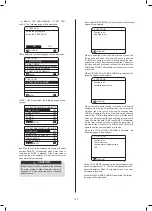
3.The automatic setting curve for heating mode
The automatic setting curve is the ninth curve,the ninth curve can be set as following:
State:In the setting the wired controller, if T4H2<T4H1, then exchange their value; if T1SETH1<T1SETH2, then exchange
their value.
T4
-10
≤
T4
<
15
15
≤
T4
<
22
22
≤
T4
<
30
30
≤
T4
1-T1S
16
11
8
5
2-T1S
17
12
9
6
3-T1S
18
13
10
7
4-T1S
19
14
11
8
5-T1S
20
15
12
9
6-T1S
21
16
13
10
7-T1S
22
17
14
11
8-T1S
23
18
15
12
T4
-10
≤
T4
<
15
15
≤
T4
<
22
22
≤
T4
<
30
30
≤
T4
1-T1S
20
18
17
16
2-T1S
21
19
18
17
3-T1S
22
20
19
17
4-T1S
23
21
19
18
5-T1S
24
21
20
18
6-T1S
24
22
20
19
7-T1S
25
22
21
19
8-T1S
25
23
21
20
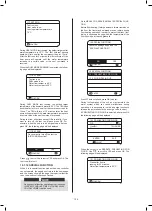
4.The environment temperature curves of the low temperature setting for cooling mode
5.The environment temperature curves of the high temperature setting for cooling mode
T4C1
T4C2
T1SETC2
T1SETC1
T4
T1S (T1S2)
6.The automatic setting curve for cooling mode
The automatic setting curve is the ninth curve,the ninth curve can be set as following:
State:In the setting the wired controller, if T4C2<T4C1,then exchange their value; if T1SETC1<T1SETC2, then exchange
their value.
125
124
Summary of Contents for MONO KHC-22RX3
Page 1: ...INSTRUKCJA INSTALACYJNA INSTALATIONMANUAL POMPA CIEPŁA MONO MONO TYPE HEAT PUMP PL EN ...
Page 2: ......
Page 79: ...79 ...
Page 80: ......
Page 157: ...NOTE 157 ...
Page 158: ...NOTE ...
Page 159: ...16125300002403 V C ...
Page 160: ...kaisai com ...


