13
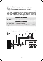
Circulation pump operation
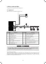
The circulation pump (1.7) and (10) will operate as long as the unit is on for space heating.
The circulation pump (1.7) will operate as long as the unit is on for heating domestic hot water (DHW).
Space heating
1) The unit (1) will operate to achieve the target water flow temperature set on the wired controller.
2) The bypass valve should be selected so that at all times the minimum water flow as mentioned in
9.4 Water piping
is
guaranteed.
Domestic water heating
1) When the domestic water heating mode is enabled (either manually by the user, or automatically through scheduling)
the target domestic hot water temperature will be achieved by a combination of the heat exchanger coil and the electrical
booster heater (when the booster heater in the tank is set to YES).
2) When the domestic hot water temperature is below the user configured set point, the 3-way valve will be activated to
heat the domestic water by means of the heat pump. If there is a huge demand for hot water or a high hot water tempera-
ture setting, the booster heater (12.3) can provide auxiliary heating.
The unit can be configured so that at low outdoor temperatures, water is exclusively heated by the booster heater. This
assures that the full capacity of the heat pump is available for space heating.
Details on domestic hot water tank configuration for low outdoor temperatures (T4DHWMIN) can be found in
10.7 Field
settings/How to set the DHW MODE
.
NOTE
Make sure to fit the 3-way valve correctly. For more details, refer to
9.7.6 Connection for other components/For
3-way valve SV1
.
CAUTION
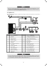
8.3 Application 3
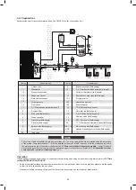
Space cooling and heating application with a room thermostat suitable for heating/cooling changeover when connected to the
unit. Heating is provided through floor heating loops and fan coil units. Cooling is provided through the fan coil units only.
Domestic hot water is provided through the domestic hot water tank which is connected to the unit.
FHL1
FHL2
FHLn
----
----
FCU1
FCU2
FCUn
----
----
2 3
6
7
8.1
8.2
8
12.1
12.2
12.3
12
T
13
14
15
16
11
11
19
10
9
4
5
18
12.1
21
20
17
1
1.5
1.4
1.2
1.3
1.7
1.6
1.1
14
The volume of balance tank(8) should be greater than 40L.The drain valve (6) should be installed at the lowest positon
of the system. Pump(10) should be controlled by outdoor unit and connect to corresponding port in the outdoor unit(refer
to
9.7.6 Connection for other components/For outside circulation pump P_o
).
NOTE
Pump operation and space heating and cooling
The unit will switch to either heating or cooling mode according to the setting of room thermostat. When space heating/cool-
ing is requested by the room thermostat (5), the pump will start operating and the unit (1) will switch to heating mode/cooling
mode. The unit (1) will operate to achieve the target cold/hot water leaving temperature. In the cooling mode. the motorized
3-way valve (19) will close to prevent cold water running through the floor heating loops (FHL).
The ON/OFF setting of the heating/cooling operation cannot be done on the user interface, the target outlet water temperature
should be set in the user interface.
Domestic water heating
Domestic water heating is as described in 8.2 Application 2.
Make sure to connect the thermostat wires to the correct terminals and to configure the ROOM THERMOSTAT in the
wired controller correctly (see
10.7 Field settings/ROOM THERMOSTAT
). Wiring of the room thermostat should follow
method A as described in
9.7.6 connection for other components/For room thermostat
.
Wiring of the 3-way valve (19) is different for a NC (normal closed) valve and a NO (normal open) valve! Make sure to
connect to the correct terminal numbers as detailed on the wiring diagram.
CAUTION
8.4 Application 4
Space heating with an auxiliary boiler (alternating operation).
Space heating application by either the unit or by an auxiliary boiler connected in the system.
The unit controlled contact (also called "permission signal for the auxiliary boiler") is determined by the outdoor temperature
(thermistor located at the outdoor unit). See
10.7 Field settings/OTHER HEATING SOURCE
.
Bivalent operation is possible for both space heating operation and domestic water heating operation.
If the auxiliary boiler only provides heat for space heating, the boiler must be integrated in the piping work and in the field
wiring according to the illustration for application a.
If the auxiliary boiler is also providing heat for domestic hot water, the boiler can be integrated in the piping work and in the
field wiring according to the illustration for application b. In this condition, the unit can sent ON/OFF signal to boiler in heating
mode, but the boiler control itself in DHW mode.
1
1.1
1.2
1.3
1.4
1.5
1.6
1.7
2
3
Assembly unit
Assembly unit
Coding
Coding
6
7
8
8.1
8.2
9
10
11
FHL 1…n
12
12.1
12.2
12.3
13
14
15
16
18
4
5
Outdoor unit
Manometer
Pressure relief valve
Expansion vessel
Plate heat exchanger
Air purge valve
Flow switch
P_i: Circulation pump inside the unit
Y-shape filter
Stop valve (field supply)
Wired controller
Drain valve (field supply)
Fill valve (field supply)
Balance tank (field supply)
Air purge valve
Room thermostat (field supply)
19
FCU 1...n
Drain valve
Expansion vessel (field supply)
P_o: Outside circulation pump (field supply)
Collector / distributor
(field supply)
Floor heating loop (field supply)
Domestic hot water tank (field supply)
Air purge valve
Heat exchanger coil
Booster heater
T5: DHW tank temp. sensor
Hot water tap (field supply)
P_d: DHW pump (field supply)
One way valve (field supply)
SV1: 3-way valve (field supply)
SV2: 3-way valve (field supply)
Fan coil units (field supply)
17
Bypass valve(field supply)
20
21
Solar energy kit(field supply)
P_s: Solar pump(field supply)
97
96
Summary of Contents for MONO KHC-22RX3
Page 1: ...INSTRUKCJA INSTALACYJNA INSTALATIONMANUAL POMPA CIEPŁA MONO MONO TYPE HEAT PUMP PL EN ...
Page 2: ......
Page 79: ...79 ...
Page 80: ......
Page 157: ...NOTE 157 ...
Page 158: ...NOTE ...
Page 159: ...16125300002403 V C ...
Page 160: ...kaisai com ...


