background image

21

RU

GB

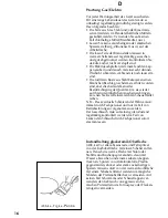
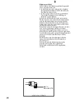
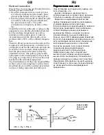
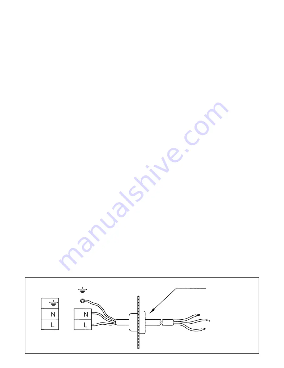
Abb. 6 - Fig. 6 - 

êËÒ. 6

KABELKLEMME
CABLE-CLAMP

êÄáöÖå

Electrical connection

(Fig. 6) Prior to carrying out the electrical con-

nection, please ensure that:

• the plant characteristics are such as to fol-

low what is indicated on the matrix plate

placed at the bottom of the working area;

• that the plant is fitted with an efficient earth

connection, following the standards and

law provisions in force.  The earth

connection is compulsory in terms of the

law.

Should there be no cable and/or plug on the

equipment, use suitable absorption material

for the working temperature as well, as

indicated on the matrix plate.  Under no

circumstance must the cable reach a tem-

perature above 50°C of the ambient tempera-

ture.

Should a direct connection to the network be

required, it will be necessary to interpose an

omnipolar switch with minimum aperture be-

tween the 3 mm. contacts, dimensioned to

bear the plate load and it must follow the

standards in force (the yellow/green earth

cable must not be interrupted by the switch).

The plug or omnipolar switch must be easily

reached on the installed equipment.

The manufacturers decline any responsibility

in the event of non-compliance with what is

described above and the accident prevention

norms not being respected and followed.

èÓ‰Íβ˜ÂÌËÂ Í ˝Î. ÒÂÚË

èÓ‰Íβ˜ÂÌËÂ Í ˝Î. ÒÂÚË

èÓ‰Íβ˜ÂÌËÂ Í ˝Î. ÒÂÚË

èÓ‰Íβ˜ÂÌËÂ Í ˝Î. ÒÂÚË

èÓ‰Íβ˜ÂÌËÂ Í ˝Î. ÒÂÚË

(êËÒ. 6) èÂʉ ˜ÂÏ ÔÓ‰Íβ˜‡Ú¸ ÔË·Ó Í ˝Î.
ÒÂÚË, ۷‰ËÚÂÒ¸, ˜ÚÓ:
- ‰‡ÌÌ˚Â, Û͇Á‡ÌÌ˚ ‚ ÛÍÓ‚Ó‰ÒÚ‚Â ÔÓ
˝ÍÒÔÎÛ‡Ú‡ˆËË ÔÎËÚ˚ ÒÓÓÚ‚ÂÚÒÚ‚Û˛Ú ‰‡ÌÌ˚Ï ‚
Ú‡·Î˘Í ̇ ÌËÊÌÂÈ ˜‡ÒÚË Ò‡ÏÓ„Ó ÔË·Ó‡
- á‡ÁÂÏÎÂÌ ÎË Ì‡‰ÎÂʇ˘ËÏ Ó·‡ÁÓÏ Ò‡Ï
ÔË·Ó. á‡ÁÂÏÎÂÌË fl‚ÎflÂÚÒfl ÌÂÓ·ıÓ‰ËÏ˚Ï
ÛÒÎÓ‚ËÂÏ Ô‡‚ËθÌÓÈ ˝ÍÒÔÎÛ‡Ú‡ˆËË.
ÖÒÎË ‚ ÍÓÏÔÎÂÍÚ Ì ÔËÍ·‰˚‚‡ÂÚÒfl ͇·Âθ Ë/
ËÎË ¯ÚÂÍÂ, ÔËÏÂÌflÈÚ ÚÓθÍÓ Ï‡ÚÂˇÎ˚,
ÒÓÓÚ‚ÂÚÒÚ‚Û˛˘Ë ‰‡ÌÌ˚Ï, Û͇Á‡ÌÌ˚Ï ‚
ÛÍÓ‚Ó‰ÒÚ‚Â. 䇷Âθ ÌË ‚ ÍÓÂÏ ÒÎÛ˜‡Â ÌÂ
‰ÓÎÊÂÌ Ì‡„‚‡Ú¸Òfl ‚˚¯Â ÚÂÏÔÂ‡ÚÛ˚,
·Óθ¯Â, ˜ÂÏ Ì‡ 50°ë Ô‚˚¯‡˛˘ÂÈ ÍÓÏ̇ÚÌÛ˛.
Ç ÒÎÛ˜‡Â ÔÓ‰ÒÓ‰ËÌÂÌËfl ÌÂÔÓÒ‰ÒÚ‚ÂÌÌÓ Í ˝Î.
ÒÂÚË, ÌÂÓ·ıÓ‰ËÏÓ ËÒÔÓθÁÓ‚‡Ú¸ ÒÔˆˇθÌ˚È
‚ÒÂÔÓÎflÌ˚È ‚˚Íβ˜‡ÚÂθ Ò ÓÚÍ˚ÚËÂÏ
ÍÓÌÚ‡ÍÚÓ‚ Ì ÏÂÌ 3 ÏÏ, ÒÓÓÚ‚ÂÚÒÚ‚ÂÌÌÓ
ÚÂıÌ˘ÂÒÍËÏ ‰‡ÌÌ˚Ï ‰ÂÈÒÚ‚Û˛˘Ëı
Ô‰ÔËÒ‡ÌËÈ (ÊÂÎÚÓ-ÁÂÎÂÌ˚È Í‡·Âθ
Á‡ÁÂÏÎÂÌËfl ‰ÓÎÊÂÌ ·˚Ú¸ ÔÓ‰Íβ˜ÂÌ Í
‚˚Íβ˜‡ÚÂβ). òÚÂÍÂ ËÎË ‚ÒÂÔÓÎflÌ˚È
‚˚Íβ˜‡ÚÂθ ̇ Ô‡‚ËθÌÓ ÛÒÚ‡ÌÓ‚ÎÂÌÌÓÏ
ÔË·Ó ‰ÓÎÊÂÌ ·˚Ú¸ ‚Ò„‰‡ ΄ÍÓ ‰ÓÒfl„‡ÂÏ.
èËϘ‡ÌËÂ: àÁ„ÓÚÓ‚ËÚÂθ Ì ÌÂÒÂÚ ÌË͇ÍÓÈ
ÓÚ‚ÂÚÒÚ‚ÂÌÌÓÒÚË, ÂÒÎË ÔË ÛÒÚ‡ÌÓ‚Í ÔË·Ó‡
Ì Òӷ≇˛ÚÒfl ‚Ò ‚˚¯ÂÔ˂‰ÂÌÌ˚Â
Ô‰ÔËÒ‡ÌËfl.

Summary of Contents for KC 40.060 Series

Page 1: ...Ö ÇëíêÄàÇÄÖåõÖ çÄÉêÖÇÄíÖãúçõÖ ÇëíêÄàÇÄÖåõÖ çÄÉêÖÇÄíÖãúçõÖ èéÇÖêïçéëíà èéÇÖêïçéëíà èéÇÖêïçéëíà èéÇÖêïçéëíà èéÇÖêïçéëíà Á ÎÂÍÚ Ó Á ÎÂÍÚ Ó Á ÎÂÍÚ Ó Á ÎÂÍÚ Ó Á ÎÂÍÚ Ó ìÒÚ ÌÓ Í àÒÔÓÎ ÁÓ ÌË ìıÓ ìÒÚ ÌÓ Í àÒÔÓÎ ÁÓ ÌË ìıÓ ìÒÚ ÌÓ Í àÒÔÓÎ ÁÓ ÌË ìıÓ ìÒÚ ÌÓ Í àÒÔÓÎ ÁÓ ÌË ìıÓ ìÒÚ ÌÓ Í àÒÔÓÎ ÁÓ ÌË ìıÓ RU KG 40 600 KCG 31 600 KG 60 800 KG 31 600 KCG 22 600 KG 50 700 KG 22 600 KG 20 290 KCG 40 600 KCG 20 290 ...

Page 2: ...RAUCH ODER MISSBRAUCH ZURÜCKZUFÜHREN SIND ÜBERNIMMT DER HERSTELLER KEINERLEI VERANTWORTUNG SEHR GEEHRTER KUNDE wir danken Ihnen und beglückwünschen Sie zu Ihrer Wahl Dieses neue Produkt sorgfältig entworfen und mit erstklassigen Materialien hergestellt wurde genau geprüft um alle Ihre Forderungen an ein perfektes Kochen zu erfüllen Wir bitten Sie deshalb die einfachen Anweisungen zu lesen und einz...

Page 3: ... Dfc pf Dfi ds jh b gjplhfdkztv c elfxyjq gjregrjq njn yjdsq ghjlern nofntkmyj hfphf jnfyysq b bpujnjdktyysq bp gthdjrkfccys vfnthbfkjd sk jcyjdfntkmyj jghj jdfy xnj s extcnm dct Dfib nht jdfybz r cjdthitycndjdfyb ghjwtccf ghbujnjdktybz k l Gj njve vs ghjcbv Dfc dybvfntkmyj ghjxbnfnm nj herjdjlcndj gj rcgkefnf wbb b cj k lfnm ghjcnst erfpfybz xnj gjpdjkztn c cfvjuj yfxfkf ghbvtytybz ecnhjqcndf ljc...

Page 4: ...dafür bestimmte Anzündungsknöpfchen drückt Bei den Modellen mit automatischer simultaner Zündung einhändig nur den entsprechenden Bedienknopf wie oben beschrieben betätigen Die elektrische Entladung zwischen diesem Element und dem Brenner verursacht die Anzündung der gewünschten Brennstelle Sobald der Brenner an ist den Knopf sofort loslassen und die Flamme nach Wunsch regeln Die Brennerzündung be...

Page 5: ... a good norm to close the main gas pipe tap and or cylinder ìÍ Á ÌËfl ìÍ Á ÌËfl ìÍ Á ÌËfl ìÍ Á ÌËfl ìÍ Á ÌËfl Îfl ÔÓÎ ÁÓ ÚÂÎfl Îfl ÔÓÎ ÁÓ ÚÂÎfl Îfl ÔÓÎ ÁÓ ÚÂÎfl Îfl ÔÓÎ ÁÓ ÚÂÎfl Îfl ÔÓÎ ÁÓ ÚÂÎfl ìÒÚ ÌÓ Í ìÒÚ ÌÓ Í ìÒÚ ÌÓ Í ìÒÚ ÌÓ Í ìÒÚ ÌÓ Í ÇÒ ÓÚ ÔÓ ÛÒÚ ÌÓ Í ÔÓ ÍÎ ÂÌËÂ Í Î ÒÂÚË ÔÓ ÍÎ ÂÌËÂ Í ÁÓÔ Ó Ó Û Ô ËÒÔÓÒÓ ÎÂÌËÂ Í Û ÓÏÛ ÚËÔÛ Á ÒÓÓÚ ÂÚÒÚ Û Ë ÛÒÚ ÌÓ ÍË Ë Ú ÓÎÊÌ Ô Ó Ó ËÚ Òfl ÒÓÓÚ ÂÚÒÚ ËË Ò ÂÈÒÚ Û ËÏË Ô Â ÔËÒ ÌË...

Page 6: ...schaltung des Apparats allerdings als normal zu betrachten N B für den Gebrauch der Elektro Kochplatten Heizelemente glaskeramik empfehlen wir die Verwendung vonTöpfen mit geradem Boden mit gleichem oder nur wenig größerem Durchmesser als die Kochplatte selbst vermeiden Sie das überlaufen von Flüssigkeiten indem Sie nach Erreichen des Siedepunktes oder Erhitzen der Flüssigkeit die Wärmezufuhr zurü...

Page 7: ...Ì ÏË ÎÂÏÂÌÚ ÏË êËÒ 2 2 3 3 ÎÂÏÂÌÚ ÏË êËÒ 2 2 3 3 ÎÂÏÂÌÚ ÏË êËÒ 2 2 3 3 ÎÂÏÂÌÚ ÏË êËÒ 2 2 3 3 ÎÂÏÂÌÚ ÏË êËÒ 2 2 3 3 ìÒÚ ÌÓ ËÚ Ô ÂÍÎ ÚÂÎ Ì ÊÂÎ ÂÏÛ ÔÓÁËˆË ì ËÚ ÈÚÂ Ô Ë ÚÓÏ ÚÓ Ò ÒÚÛ ÂÈ ˆËÙ ÓÈ Û ÂÎË Ë ÂÚÒfl Ú ÍÊÂ Ë ÏÓ ÌÓÒÚ Ì Â ÎÂÏÂÌÚÓ ÒÏÓÚ ËÚÂ Ú ÎËˆÛ è ËÏÂÌÂÌË ÎÂÍÚ Ë ÂÒÍËı Ì Â ÚÂÎ Ì ı ÔÓ Â ıÌÓÒÚÂÈ ëÚÂÍÎÓÍ ÏË ÂÒÍËÂ Ì Â ÚÂÎ Ì Â ÎÂÏÂÌÚ äÓÌÚ ÓÎ Ì Â Î ÏÔÓ ÍË Ì Ô  ÌÂÈ Ô ÌÂÎË ËÎË Ì Ô ÌÂÎË Ô ÂÍÎ ÂÌËfl ÛÍ Á...

Page 8: ...fish 20x32 wok Ø 20 32 fast Ø 20 26 semifast Ø 14 20 auxiliary Ø 10 14 ÛÒflÚÌˈ 20x32 ÍÓÚÂÎÓÍ Ø 20 32 ÒÚ fl Ø 20 26 ÔÓÎÛ ÒÚ fl Ø 14 20 ÒÔÓÏÓ ÚÂÎ Ì fl Ø 10 14 Abb 2 Fig 2 êËÒ 2 ABGESCHALTET SWITCHED OFF ÇõäãûóÖçé KOCHPLATTEN ELECTRICAL PLATES ùãÖäíêàóÖëäàÖ äéçîéêäà mit Reduziergitter with reduction grid GAS GAS ÉÄá ...

Page 9: ...9 RU GB Abb 2a Fig 2a êËÒ 2a GLASKERAMIK HEIZELEMENTE VITROCERAMIC HEATING ELEMENTS ëíÖäãéäÖêÄåàóÖëäàÖ çÄÉêÖÇÄíÖãúçõÖ ùãÖåÖçíõ nein no ÌÂÚ ÌÂÚ ÌÂÚ ÌÂÚ ÌÂÚ nein no ÌÂÚ ÌÂÚ ÌÂÚ ÌÂÚ ÌÂÚ ja yes ...

Page 10: ...10 D Abb 3 Fig 3 êËÒ 3 ...

Page 11: ...11 RU GB Abb 3a Fig 3a êËÒ 3a ...

Page 12: ...12 D Abb 3b Fig 3b êËÒ 3b CRYSTAL ...

Page 13: ...13 RU GB Abb 3c Fig 3c êËÒ 3c GLASKERAMIK VITROCERAMIC ...

Page 14: ...14 D Abb 4 Fig 4 êËÒ 4 KG 20 290 KGC 20 290 KG 50 700 KG 60 800 KG 40 600 KG 31 600 KG 22 600 KCG 40 600 KCG 31 600 KCG 22 600 ...

Page 15: ...  ÚÂÎ Ì Â ÎÂÏÂÌÚ è ÂÍÎ ÚÂÎ è ÂÍÎ ÚÂÎ è ÂÍÎ ÚÂÎ è ÂÍÎ ÚÂÎ è ÂÍÎ ÚÂÎ ëÚÛÔÂÌË ëÚÛÔÂÌË ëÚÛÔÂÌË ëÚÛÔÂÌË ëÚÛÔÂÌË àÌÚÂÌÒË ÌÓÒÚ àÌÚÂÌÒË ÌÓÒÚ àÌÚÂÌÒË ÌÓÒÚ àÌÚÂÌÒË ÌÓÒÚ àÌÚÂÌÒË ÌÓÒÚ ÇË Ô Ë ÓÚÓ ÎÂÌËfl ÇË Ô Ë ÓÚÓ ÎÂÌËfl ÇË Ô Ë ÓÚÓ ÎÂÌËfl ÇË Ô Ë ÓÚÓ ÎÂÌËfl ÇË Ô Ë ÓÚÓ ÎÂÌËfl Ì Â Ì Â Ì Â Ì Â Ì Â Ì Â Ì Â Ì Â Ì Â Ì Â 1 1 2 Ó ÂÌ ÒÎ È ÊË Ì Â ÊË ÍÓÒÚË Ë Ú Ô ÁÓ Â Ï Î ı ÍÓÎË ÂÒÚ ÊË ÍÓÒÚË 2 3 4 ΠÍËÈ ÁÓ Â Ò Â ÌËı ÍÓÎË...

Page 16: ...keinerlei Beeinträchtigung der Qualität Um sie wieder auf ihren ursprünglichen Anschein zu bringen kön nen Sie sie mit einem leichten Scheuermittel reiben N B Das eventuelle Schmieren der Hähne muß immer durch Fachpersonal und nur im Fall von Betriebsstörungen vorgenommen werden Der Gasschlauch muß auf seinen guten Zustand regelmäßig kontrolliert werden Im Fall von Lecken den Schlauch durch Fachpe...

Page 17: ...rface of the top Under no circumstances should abrasive sponges or irritating chemical detergents be used such as oven sprays or spot removers ìıÓ Á ÔÎËÚÓÈ É Á ÎÂÍÚ Ó ìıÓ Á ÔÎËÚÓÈ É Á ÎÂÍÚ Ó ìıÓ Á ÔÎËÚÓÈ É Á ÎÂÍÚ Ó ìıÓ Á ÔÎËÚÓÈ É Á ÎÂÍÚ Ó ìıÓ Á ÔÎËÚÓÈ É Á ÎÂÍÚ Ó èÂ Â Í Ê ÓÈ ËÒÚÍÓÈ ÓÚÍÎ Ú Ô Ë Ó ÑÎfl Ô Ó ÎÂÌËfl Ò ÓÍ ÒÎÛÊ Ô Ë Ó ÌÂÓ ıÓ ËÏÓ Â Ó Â ÛÎfl ÌÓ Ë ÓÒÌÓ ÚÂÎ ÌÓ ËÒÚËÚ è Ë ÚÓÏ ÌÂÓ ıÓ ËÏÓ Ô ËÌËÏ Ú Ó Ì...

Page 18: ... Fläche mit dem mit gelieferten Abdichtungsmittel versiegeln Gasanschluß s Abb 5 Das Gerät an die Gasflasche oder an das Gasversorgungsnetz nach den geltenden Vorschriften anschließen und dabei sicherstellen daß das Gerät auf den vorhandenen Gastyp eingestellt ist wenn es nicht der Fall sein sollte wird auf das Kapitel Anpassung an einen anderen Gastyp verwiesen Man sollte außerdem kontrollieren d...

Page 19: ... Í ë Ó Í ë Ó Í ë Ó Í ùÚÓÚ Ô Ë Ó Ì ÔÓ ÒÓ ËÌÂÌ Í ÛÒÚ ÓÈÒÚ Û ÚflÊÍË ÁÓ Ò Ó ÌËfl ìÒÚ ÌÓ Í Ë ÔÓ ÒÓ ËÌÂÌË ÓÎÊÌ Ô ÓËÁ Ó ËÚ Òfl ÒÓÓÚ ÂÚÒÚ ËË Ò Ì ÒÚÓfl ËÏ Ô Â ÔËÒ ÌËÂÏ è Ë Ó ÛÒÚ Ì ÎË ÂÚÒfl ÚÓÎ ÍÓ ÓÒÚ ÚÓ ÌÓ ıÓ Ó Ó Ô Ó ÂÚ Ë ÂÏÓÏ ÔÓÏ ÂÌËË Ò Û ÂÚÓÏ ÒÂı Ô Â ÔËÒ ÌËÈ é ÂÏ ÔÓ Ë ÓÁ Ûı ÌÂÓ ıÓ ËÏÓ Ó Îfl Ô ÓˆÂÒÒ Ò Ó ÌËfl Ì ÓÎÊÂÌ Ú ÏÂÌ Â 2 Ï3 Ò Ì Í Ê È ÍËÎÓ ÚÚ ÛÒÚ Ì ÎË ÂÏÓÈ ÏÓ ÌÓÒÚË ÒÏ Ú Îˈ ÏÓ ÌÓÒÚË Ì Â ìÒÚ ÌÓ Í ìÒÚ Ì...

Page 20: ...l Das Kabel darf an keiner Stelle eine Temperatur erreichen die mehr als 50 C über der Raumtemperatur liegt Falls direkt an das Netz angeschlossen werden soll wird ein allpoliger Schalter mit einer minimalen Öffnung der Kontakte von 3 mm entsprechend der Kenndaten und der geltenden Vorschriften das gelb grüne Erdungskabe darf nicht vom Schalter unterbrochen werden benötigt Die Steckdose oder der a...

Page 21: ...olar switch must be easily reached on the installed equipment The manufacturers decline any responsibility in the event of non compliance with what is described above and the accident prevention norms not being respected and followed èÓ ÍÎ ÂÌËÂ Í Î ÒÂÚË èÓ ÍÎ ÂÌËÂ Í Î ÒÂÚË èÓ ÍÎ ÂÌËÂ Í Î ÒÂÚË èÓ ÍÎ ÂÌËÂ Í Î ÒÂÚË èÓ ÍÎ ÂÌËÂ Í Î ÒÂÚË êËÒ 6 è ÂÊ Â ÂÏ ÔÓ ÍÎ Ú Ô Ë Ó Í Î ÒÂÚË Û Â ËÚÂÒ ÚÓ ÌÌ Â ÛÍ Á ÌÌ Â ...

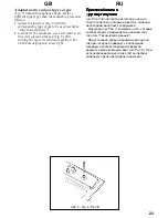
Page 22: ...ren die Düsen s Abb 7 mit den für den vorhandenen Gastyp bestimmten Düsen siehe Tab Technische Daten ersetzen bei der Einstellung des Mindestwertes den Hahnhebel auf das Minimum drehen und die Einstellschraube am Hahn mit entsprechendem Schraubenzieher drehen s Abb 8 Bei Betrieb mit Flüssiggas Butan Propangas Einstellschraube fest anziehen Abb 7 Fig 7 êËÒ 7 ...

Page 23: ... position For LPG butane propane screw tight è ËÒÔÓÒÓ ÎÂÌËÂ Í è ËÒÔÓÒÓ ÎÂÌËÂ Í è ËÒÔÓÒÓ ÎÂÌËÂ Í è ËÒÔÓÒÓ ÎÂÌËÂ Í è ËÒÔÓÒÓ ÎÂÌËÂ Í Û ÓÏÛ ÚËÔÛ Á Û ÓÏÛ ÚËÔÛ Á Û ÓÏÛ ÚËÔÛ Á Û ÓÏÛ ÚËÔÛ Á Û ÓÏÛ ÚËÔÛ Á ÒÏ êËÒ 7 ÖÒÎË Ô Ë Ó ËÁ ÓÚÓ ÎÂÌ Ì Îfl Ú ÍÓ Ó ÚËÔ Á ÍÓÚÓ È ËÏÂÂÚÒfl Ì ÎË ËË ÌÂÓ ıÓ ËÏÓ ÔÓÎÌËÚ ÒÎÂ Û Â ÙÓ ÒÛÌÍË ÒÏ êËÒ 7 Á ÏÂÌËÚ Ì Ú ÍÓÚÓ Â ÒÓÓÚ ÂÚÒÚ Û Ú ËÏ ÂÏÛÒfl Ì ÎË ËË ÚËÔÛ Á ÒÏ íÂıÌË ÂÒÍË ÌÌ Â è Ë ÛÒÚ ...

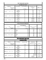
Page 24: ...286 semifast 105 1750 167 auxiliary 83 1000 95 wok 135 3500 333 fish 130 3000 286 fast 85 3000 218 semifast 65 1750 127 auxiliary 50 1000 73 wok 92 3500 254 fish 85 3000 218 natural gas G20 20 liquefied gas G30 G31 28 30 37 íÖïçàóÖëäàÖ ÑÄççõÖ íÖïçàóÖëäàÖ ÑÄççõÖ íÖïçàóÖëäàÖ ÑÄççõÖ íÖïçàóÖëäàÖ ÑÄççõÖ íÖïçàóÖëäàÖ ÑÄççõÖ ÉÄáéÇõÖ ÉéêÖãäà ÉÄáéÇõÖ ÉéêÖãäà ÉÄáéÇõÖ ÉéêÖãäà ÉÄáéÇõÖ ÉéêÖãäà ÉÄáéÇõÖ ÉéêÖãäà è...

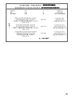
Page 25: ...ãàêéÇÄçàÖ DREIFACHER STRAHLUNGSKREIS HI LIGHT Kommutator 0 6 TRIPLE CIRCUIT RADIANT HI LIGHT 1200 1700 commutator 0 6 çéêå ë íêéâçéâ ëèàêÄãúû HI LIGHT Ô ÂÍÎ ÚÂÎ 0 6 Ø145 Ø180 EINZEL STRAHLUNGSKREIS HI LIGHT Energieregler 0 11 SINGLE CIRCUIT RADIANT HI LIGHT 1200 1700 energy regulator 0 11 çéêå ë éÑàçÄêçéâ ëèàêÄãúû HI LIGHT  ÛÎflÚÓ Ì ËË 0 11 Ø145 Ø180 GEMISCHTER HALOGEN STRAHLUNGSKREIS Energiereg...

Page 26: ......

Page 27: ......
Page 28: ...fpsdf n ceotcndtyyjuj dkbzybz yf gjnht bntkmcrbt rfxtcndf b cdjqcndf ghjlernf Die Herstellerfirma übernimmt keinerlei Verantwortung für eventuell in dieser Broschüre enthaltene Ungenauigkeiten die auf Druckfehler zurückzuführen sind und behält sich das Recht vor an ihren Produkten alle für notwendig erachteten Änderungen anzubringen ohne die wesentlichen Eigenschaften zu beeinflussen OLAN Haushalt...

Reviews: