background image

Operation Manual

3-IN-1/30

Model 3-IN-1/30

- 6 -

4. All metal cut on this machine will have
a sharp edge. File or sand the sharp edge
before handling to avoid injury.

Figure 7

Lower Blade Adjustment

Upper and lower shear blades have been
factory aligned and should not require
immediate

adjustment.

Should

re-alignment be needed in the future,
proceed as follows:
1. Place a heavy sheet of paper in the
cutting position, along entire length of bed,
and make a cut.
2. If the shear does not cut the paper,
loosen screw (L, Figure 7) at each end of
table, with 8mm hex key.
3. Rotate adjustment screws (M, Figure 8)
to shift table and change the gap between
blades.

Do not allow the blades to

overlap.

4. If the shear cuts the paper on the ends,
but not the center, slightly turn screw (N,

Figure 9) clockwise until paper is cut the
entire length.

Figure 8

5.If the shear cuts the paper in the center,
but not the ends, turn screw (N)
counterclockwise until paper is cut the
entire length.

Figure 9

Blade Rotation/Replacement

Exercise caution when

working with or near the blades. Use
work gloves when handling them

.

Summary of Contents for 171003

Page 1: ...king the unit carefully inspect for any damage that may have occurred during transit If damage has occurred shipping damage claims must be filed with the carrier and are the responsibility of the user Check for completeness Immediately report missing parts to dealer Warning The warnings cautions and instructions discussed in this instructions or situations that could occur It must be understood by...

Page 2: ...es Everyday eyeglasses only have impact resistant lenses They are NOT safety glasses Dust mask non skid safety shoes hard hat or hearing protection should be used in appropriate conditions 6 Wear proper apparel Loose clothing gloves neckties rings bracelets or other jewelry may present a potential hazard when operating this machine Please keep all apparel clear of the machine 7 Don t overreach Kee...

Page 3: ... Carefully move machine to a work bench or stand Machine location must allow free access on all sides 6 Bolt machine to stand or workbench The stand or workbench must be bolted to the floor NOTE An optional stand is available for this machine see Section 8 Contact KAKA distributor to order 7 Remove one handle A Figure 2 from each operating handle assembly using 8mm hex key Figure 2 8 Loosen lock b...

Page 4: ...bottom die the full length of die 2 Close brake until the wood contacts upper dies E 3 Loosen screws D using 6mm hex key Figure 5 4 Select upper dies E for desired job and remove the others by sliding them out the left end Included die set sizes 1 2 3 6 8 and 10 5 Move operating handle until the wood pushes up the dies so that they seat uniformly in upper beam 6 Securely re tighten all screws Figu...

Page 5: ...nd the desired angle since the metal will have some degree of spring back Shear set up Do not shear material larger than 30 20 gauge mild steel Failure to comply may cause serious injury and or damage to the machine 1 Install guide rods and plate in shear position Figure 4 and adjust to desired length of workpiece cut 2 Place workpiece against guide block at right edge of table K Figure 7 The end ...

Page 6: ...and make a cut 2 If the shear does not cut the paper loosen screw L Figure 7 at each end of table with 8mm hex key 3 Rotate adjustment screws M Figure 8 to shift table and change the gap between blades Do not allow the blades to overlap 4 If the shear cuts the paper on the ends but not the center slightly turn screw N Figure 9 clockwise until paper is cut the entire length Figure 8 5 If the shear ...

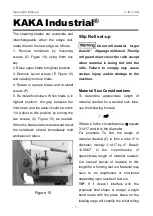
Page 7: ... roll material larger than 30 20 gauge mild steel The slip roll guard must cover the rolls except when material is being fed into the rolls Failure to comply may cause serious injury and or damage to the machine Material Size Considerations To determine approximate length of material needed for a desired size tube use the following formula C πD Where C is the circumference π equals 3 1417 and D is...

Page 8: ...rly 5 Rotate both idle roll screws Q Figure 11 to adjust idle roll s proximity to the two main rollers Raise both ends an equal amount 6 Run workpiece through the machine using the handles If workpiece is large make sure it receives proper support as it exits the machine 7 Make further passes of workpiece raising the idle roll incrementally before each pass until desired radius is achieved No exac...

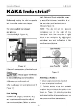
Page 9: ...e slip roll machine to straighten flatten or reduce their thickness Simply adjust the upper press roll for thickness lower idle roll all the way down and feed workpiece through Figure 13 NOTE The idle roll will not descend completely out of the path of the workpiece thus there may be a slight bend in the workpiece By flipping the workpiece over and re feeding it this bend can be minimized Figure 1...

Page 10: ...ccommodate a 5 32 11 64 and a 7 32 wire Use the smallest groove into which the wire will comfortably fit Bend the wire using the same principles as described for forming a radius To make a complete loop of wire use the instructions for forming a tube Maintenance Lubrication Use caution when doing maintenance work around the shear blades 1 Apply 2 lithium tube grease once a month to the grease nipp...

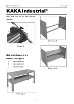
Page 11: ... 3 IN 1 30 KAKA Industrial 11 upper dies from bar for more effective cleaning Figure 16 Optional Accessories Part No Description A Optional Stand B Optional Stand C Optional Stand Stand type A Stand type B Stand type C ...

Page 12: ...p Adjust gap as needed Loose gibes Adjust backlash out of gibes BRAKE Workpiece not bending or bending difficult Workpiece too thick Use materials within capacity Improper bend allowance Adjust brake beam for proper bend size Bend radius not consistent across material Machine capacity exceeded Use materials within capacity Brake beam improperly set for bending allowance Adjust brake beam for consi...

Page 13: ...d screw 2 9 Spring 2 26 Nut M10 2 10 Press plate 1 27 Adjusting screw 2 11 Moving cutter plate 1 28 Grease fitting 2 12 1 Upper braking Die 10 1 29 Press cover 2 12 2 Upper braking Die 8 1 30 Gear 2 12 3 Upper braking Die 6 1 31 Lower roll 1 12 4 Upper braking Die 3 1 32 Upper roll 1 12 5 Upper braking Die 2 1 33 Protecting cover 1 12 6 Upper braking Die 1 1 34 Pin φ3X18 2 13 Die clamping plate 1 ...

Page 14: ...25 4 42 Pin φ4X10 2 55 Washer 2 43 Handle 4 56 Screw M8X80 2 44 Screw M6X10 2 57 Screw M10X25 2 45 Screw M10X45 2 58 Screw M6X12 2 46 Washer 4 59 Screw M6X12 14 47 Bolt M12X60 1 60 Bushing 4 48 Bolt M10X25 2 61 Nut M10 2 49 Washer 2 62 Stand type A Optional 1 50 Nut M12 3 63 Stand type B Optional 1 51 Bolt M12X40 2 64 Stand type C Optional 1 52 Screw M10X35 2 ...

Page 15: ...Operation Manual 3 IN 1 30 KAKA Industrial 15 Diagram ...

Page 16: ...Operation Manual 3 IN 1 30 Model 3 IN 1 30 16 NOTES ...

Page 17: ...Operation Manual 3 IN 1 30 KAKA Industrial 17 NOTES ...

Page 18: ...Operation Manual 3 IN 1 30 Model 3 IN 1 30 18 SERVICE RECORD KAKA Industrial Date Maintenance performed Repair components require ...

Page 19: ...Operation Manual 3 IN 1 30 KAKA Industrial 19 SERVICE RECORD KAKA Industrial Date Maintenance performed Repair components require ...

Page 20: ... kakaindustrial com Add 4200 Steve Reynolds Blvd Ste 6 Norcross GA 30093 U S A KAKA INDUSTRIAL LTD Mail echo kakaindustrial com Add 3143 Underhill Avenue Burnaby B C V5A3C8 Canada KANG INDUSTRIAL PTY LTD Mail kang kakaindustrial com Add 3 Wayne Court Dandenong VIC 3175 Australia Stock No 171003 Edition 2 01 2019 Copyright 2019 KAKA ...

Reviews: