background image

Operation Manual

YP-38

Model YP-38

- 12 -

it to the

#3

mark (as in

C

)

,

and make a

90

˚

bend.

7. Turn the stock end-for-end. Insert it to
the #4 mark (as in

D

), and make a 90

˚

bend.
8. Grind and sand all sharp corners.

Example: Bending Tube

Clamps

Single-Tube Clamp

To make a 1-in. I.D. tube clamp (for
clamping 1-in. O.D. tubing), using a

4

1

2

-in length of

3

16

-in. x 1-in. hot-rolled

flat stock:

STOCK REQUIRED (for this example)
One

4

1

2

-in. length of

3

16

-in x 1-in.

hot-rolled flat stock

1. With a long hinge pin, attach the
handle and ring loops at their center-pin
holes. Install a 1-in. die on the center pin.
With the short hinge pin, install a 1

1

2

-in.

die in the handle (#2 hole).
2. With a long hinge pin, install the stop
block (oriented as in

A

).

3. Insert the flat stock into the Bender so
that it extends

1

1

2

-in. beyond the

NOTE:

To make other sizes of clamps,

experiment to find the appropriate die
sizes and stop block orientation.

TYPICAL TUBE CLAMPS

Single-Tube
Clamp

Double-Tube

Clamp

A

#4

Orientation

1-1/2” Die

1” Die

D

C

Summary of Contents for 173214

Page 1: ...The COMPACT BENDER Y P38 is shipped from the manufacture in a carefully packed Carton box Thoroughly inspect the product upon opening the package After unpacking the unit carefully inspect for any damage that may have occurred during transit If damage has occurred shipping damage claims must be filed with the carrier and are the responsibility of the user Check for completeness Immediately report ...

Page 2: ...sed in appropriate conditions 6 Wear proper apparel Loose clothing gloves neckties rings bracelets or other jewelry may present a potential hazard when operating this machine Please keep all apparel clear of the machine 7 Don t overreach Keep proper footing and balance always when operating this product 8 Check for damage Check your tool regularly If part of the tool is damaged it should be carefu...

Page 3: ...ild solvent such as mineral spirits using a soft cloth Avoid getting cleaning solution on painted surfaces rubber or plastic parts Solvents may deteriorate these finishes Use soap and water on paint plastic and rubber components After cleaning cover all exposed surfaces with a light coating of oil Assembly 1 Take out Stand 11 bolt it to the floor securely Figure 1 2 Put spacer ring 13 on to the ho...

Page 4: ... showing you how to make some common parts at a typical size Other than those specific instructions setting up the Bender to form your particular parts will involve a certain amount of trial and error You will notice some differences in operation depending on whether you are forming the piece around a die or whether you are making a sharp angle bend in the piece However in general you will 1 Deter...

Page 5: ...acy is required you will need a suitable device for measuring the bend angles Fixed and Adjustable Stops If you are making multiple parts with the same bend angle using the same setup dies and hole locations the operation will be go faster by installing either the fixed or adjustable stop in the appropriate hole in the ring assembly After determining the handle rotation insert the fixed stop 5 int...

Page 6: ... pin 2 or another die that has been installed on the center pin When you are bending material the stop block will be located using a hitch pin at one of the five large holes in the middle of the ring assembly s loop The large hole at the open end of the loop is for the center pin You will have to determine by trial which hole you will use depending on the thickness of the material being bent the s...

Page 7: ... as close to the center pin or die as possible while leaving space for the material to be inserted If there is too much space between the stop block and the center pin or die turn the block to a different orientation or move the block one hole closer to the center Positioning the Block Support The block support must be located under the stop block as shown as figure 11 to keep the block centered v...

Page 8: ...tachment IMPORTANT Read the previous section before you proceed to this section Purpose of the Attachment The sharp angle bend attachment 1 is used instead of the stop block 3 when you make a right angle bend or other sharp bend in flat material Show as figure 13 Positioning the attachment In contrast to the stop block the sharp angle bend attachment has only one correct orientation as shown as fi...

Page 9: ...nto the Bender so that half the width of the chalk mark shows and the other half is covered by the bending edge of the attachment If you are making two right angle bends on the same side of the material space their chalk marks about 1 8 Farther apart than the desired inside dimension after the bend Sharp Angle Bend Attachment 3 Hole in Loop Figure 14 MAINTENANCE 1 Regular lubrication will help len...

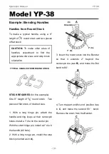
Page 10: ...stall a 1 die on the center pin With the short hinge pin install a 2 die in the handle 2 hole 2 With a long hinge pin install the stop block oriented as in A 3 Insert the round stock into the Bender so that it extends 2 beyond the center pin die see B and make the first bend to 90 4 Turn the part end for end position it as in C and make the second 90 bend Remove the stock from the Bender CAUTION T...

Page 11: ...Install the sharp angle bend attachment 2 Place chalk marks on the material as shown under Bend Sequence the 1 and 2 marks are on one face of the material and the 3 and 4 marks are on the opposite face 3 Insert the flat stock into the Bender to the 1 mark as in A and make a 90 bend Check the angle before continuing 4 Set the adjustable stop so each bend will be 90 5 Turn the stock end for end Inse...

Page 12: ...ample One 41 2 in length of 3 16 in x 1 in hot rolled flat stock 1 With a long hinge pin attach the handle and ring loops at their center pin holes Install a 1 in die on the center pin With the short hinge pin install a 11 2 in die in the handle 2 hole 2 With a long hinge pin install the stop block oriented as in A 3 Insert the flat stock into the Bender so that it extends 11 2 in beyond the NOTE ...

Page 13: ...oop 7 Make the second bend by pulling the handle until it is about 1 8 in From the stop pin Double Tube Clamp To make a 1 in I D tube clamp for clamping two lengths of 1 in O D tubing using a 41 2 in length of 3 16 in x 1 in hot rolled flat stock STOCK REQUIRED for this example One 61 2 in length of 3 16 in x 1 in hot rolled flat stock 1 With a long hinge pin attach the handle and ring loops at th...

Page 14: ...til the handle die runs off the end of the piece 7 Remove the stop block and install the sharp angle bend attachment 8 You will have to temporarily remove the center pin to insert the piece into the Binder Slide the piece as far left as possible against the center pin as in D 9 Make the third bend by pulling the handle until it is about 1 8 in from the stop pin 10 Reverse the part end for end Slid...

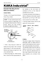
Page 15: ...lock 1 2 in for 3 8 in bolts 5 8 in for 1 2 in bolts 1 4 in for 5 8 in bolts 4 Pull the handle around until the bolt shaft is 90 from the anchor U Bolts The tables on pages 18 and 19 show the appropriate setup for making Ubolts in typical finished lengths and bend radius s from common diameters of round stock The illustration below shows the setup for making a U bolt that is 31 2 in long and 2 in ...

Page 16: ...lt that is 1 in longer add 2 in to the blank length Bend Radius Eight bend radius s are possible by selecting from the seven forming dies or by using center pin without a die However to avoid bending the center pin always use a forming die with round stock larger than 3 8 in diameter Notes Because blank stock may vary slightly in content or size we recommend making a test bend using unthreaded sto...

Page 17: ...rom 1 4 in Round Stock FINISHED SIZE Length I D SETUP FOR BENDING Blank Loop Stop Block Stop Block Center Handle Handle Length Hole No Orientation Meas t Pin Die Die Hole No 21 2 11 4 61 4 1 1 5 16 11 4 2 2 3 11 2 73 8 2 4 1 4 11 2 2 2 3 13 4 75 8 2 4 3 8 13 4 2 2 31 2 2 83 4 2 4 15 16 2 2 2 Bending U Bolts from 3 8 in Round Stock FINISHED SIZE Length I D SETUP FOR BENDING Blank Loop Stop Block St...

Page 18: ...ole No 23 4 11 2 71 4 2 4 7 16 11 2 3 3 3 13 4 8 2 4 15 16 13 4 3 3 31 4 2 83 4 2 3 3 4 2 21 2 3 4 21 2 101 8 2 2 1 21 2 2 3 41 2 3 115 8 3 4 1 3 2 3 Bending U Bolts from 5 8 in Round Stock FINISHED SIZE Length I D SETUP FOR BENDING Blank Loop Stop Block Stop Block Center Handle Handle Length Hole No Orientation Meas t Pin Die Die Hole No 31 2 2 91 4 2 2 1 2 3 3 21 2 21 2 111 2 2 1 15 8 21 2 2 3 5...

Page 19: ...ch is the most difficult to form To avoid wasting material practice some of the letters using 3 16 in stock that is only 1 2 in wide before you attempt the finished version If you have two or more identical letters make all of them before proceeding to a different letter Setup Make chalk marks on the 14 in blank as shown on the Bend Sequence Bend No 1 Insert the stock into the Bender to the 6 chal...

Page 20: ...el to the top edge Grind and sand all sharp corners Setup Make chalk marks on the two 87 8 in blanks as shown on the Bend Sequence Bend No 1 Insert one of the blanks into the Bender to the 6 chalk mark as in A and bend it to 45 Recheck the angle before you go on to the second bend Chalk mark the ring or set a stop for ease of repeating the 45 bend STOCK REQUIRED 3 16 in stock 2 in max width One 87...

Page 21: ...k as in C and bend it to 45 Recheck the angle Bend No 4 Again reverse the stock end for end Move it to the 10 chalk mark as in D and bend it to 45 Recheck the angle To remove the part from the Bender remove the pin that holds the sharp anglebend attachment Finishing Tack weld the two loops together Tack weld the 6 in piece to form the back of the letter B Grind and sand all sharp corners A Mark B ...

Page 22: ...ou go on to the second bend Bend No 2 Slide the stock to the 15 chalk mark as in B and bend it to 45 Recheck the angle Bend No 3 Slide the stock to the 24 chalk mark as in C and bend it to 45 Recheck the angle Bend No 4 Reverse the stock end for end Slide it to the 10 chalk mark as in D and bend it to 45 BEND SEQUENCE 4 5 6 3 2 1 11 4 21 2 11 4 11 4 21 2 11 4 STOCK REQUIRED 3 16 in stock 2 in max ...

Page 23: ...angle To remove the part from the Bender remove the pin that holds the sharpangle bend attachment Finishing Grind and sand all sharp corners Setup Make chalk marks on the two 12 7 8 in blank as shown on the Bend Sequence Bend No 1 Insert the blank into the Bender to the 6 chalk mark as in A and bend it STOCK REQUIRED 3 16 in stock 2 in max width One 121 2 in blank One 6 in blank BEND SEQUENCE 3 4 ...

Page 24: ...heck that the bend leg is at 90 to the front of the D Bend No 3 Reverse the stock end for end Slide it to the 24 chalk mark as in C and bend it to 45 Recheck the angle Bend No 4 Slide the stock to the 10 chalk mark as in D and bend it to 45 Recheck the angle Recheck that the two legs are parallel To remove the part from the Bender remove the pin that holds the sharpangle bend attachment Finishing ...

Page 25: ...d it to 45 Recheck the angle before you go on to the second bend Bend No 2 Slide the stock to the 15 chalk mark as in B and bend it to 90 Recheck the angle Bend No 3 Reverse the stock end for end Slide it to the 24 chalk mark as in C and bend it to 45 Recheck the angle BEND SEQUENCE 3 4 2 1 11 4 31 4 31 4 11 4 21 2 STOCK REQUIRED 3 16 in stock 2 in max width One 149 16 in blank One 21 2 in blank ...

Page 26: ...nder remove the pin that holds the sharp angle bend attachment Finishing Tack weld the 31 2 in insert piece between the legs of the A parallel to the top edge Grind and sand all sharp corners Setup Make a letter L as shown on page 31 Finishing Position the 21 2 in piece as shown and tack weld it Grind and sand all sharp corners 3 STOCK REQUIRED 3 16 in stock 2 in max width One 103 8 in blank One 2...

Page 27: ...lds the sharp angle bend attachment Finishing Position the 3 in piece as shown and tack weld it Grind and sand all sharp corners Setup None Finishing Tack weld the pieces together as shown Recheck that the pieces are at 90 angles to each other Grind and sand all sharp corners 1 STOCK REQUIRED 3 16 in stock 2 in max width One 14 in blank One 3 in Blank BEND 1 STOCK REQUIRED 3 16 in stock 2 in max w...

Page 28: ...end Bend No 2 Reverse the stock end for end Slide it to the 15 chalk mark and bend it to 45 Recheck the angle To remove the part from the Bender remove the pin that holds the sharpangle bend attachment Finishing Position the 5 5 8 in piece between the bent pieces as shown and tack weld it Recheck that the parts are 90 Grind and sand all sharp corners STOCK REQUIRED 3 16 in stock 2 in max Width BEN...

Page 29: ...ing or set a stop for ease of repeating the 45 bend Bend No 2 Slide the stock to the 15 chalk mark as in B and bend it to 45 Recheck the angle Bend No 3 Slide the stock to the 24 chalk mark as in C and bend it to 45 Recheck the angle To remove the part from the Bender remove the pin that holds the sharp angle bend attachment Finishing Grind and sand all sharp corners STOCK REQUIRED 3 16 in stock 2...

Page 30: ...d the pieces together as shown Recheck that the outer tips of the bent piece are equal distances from the straight piece Grind and sand all sharp corners Setup Make chalk marks on the blanks as shown on the Bend Sequence 6 STOCK REQUIRED BEND 7 in blank 3 16 in stock 2 in max width One 7 in blank One 6 in Blank One 21 2 in Blank 31 2 STOCK REQUIRED BEND SEQUENCE 3 16 in stock 2 in max Width 2 1 On...

Page 31: ... to 90 Recheck the angle To remove the part from the Bender remove the pin that holds the sharpangle bend attachment Finishing Grind and sand all sharp corners Setup Make two letter V s Finishing Turn the V s upside down and tack weld them together as shown Check that the three bottom tips are aligned Grind and sand all sharp corners STOCK REQUIRED 3 16 in stock 2 in max width One 131 2 in blank ...

Page 32: ... No 2 Reverse the stock end for end Slide it to the 15 chalk mark and bend it to 73 Recheck the angle To remove the part from the Bender remove the pin that holds the sharp angle bend attachment Finishing Tack weld the pieces together Recheck that the straight legs are parallel Grind and sand all sharp corners STOCK REQUIRED 3 16 in stock 2 in max width One 81 16 in Blank Two 6 in Blanks BEND SEQU...

Page 33: ...er as shown Grind and sand all sharp corners Setup Make part of a letter B page 21 the straight piece and one loop Finishing Tack weld the pieces together Grind and sand all sharp corners STOCK REQUIRED 3 16 in stock 2 in max width One 87 8 in blank One 6 in blank 37 8 STOCK REQUIRED 3 16 in stock 2 in max width One 14 in blank One 3 7 8 in blank ...

Page 34: ...harp corners Setup Make part of a letter P Finishing Tack weld the 3 1 8 in piece to the P as shown Grind and sand all sharp corners STOCK REQUIRED 3 16 in stock 2 in max width One 87 8 in blank One 6 in blank One 3 1 8 in blank 2 3 4 31 8 STOCK REQUIRED 3 16 in stock 2 in max width One 14 in blank One 37 8 in blank One 2 in blank One 3 4 in blank ...

Page 35: ...mark as in A and bend it to 45 Recheck the angle Chalk mark the ring or set a stop for ease of repeating the 45 bend Note that Bends 24 and 27 are to 41 Bend No 2 Slide the blank to the 15 chalk mark as in B and bend it to 45 STOCK REQUIRED BEND SEQUENCE 3 16 in stock 2 in max Width 5 6 9 8 7 3 4 10 2 1 One 161 2 in blank 1 25 8 1 1 1 4 1 1 1 1 4 1 25 8 1 Mark CAUTION Because of the number of bend...

Page 36: ...ack to the 10 chalk mark as in D and bend it to 45 Bend No 5 Reverse the stock end for end Slide the blank to the 16 chalk mark as in E and bend it to 45 Recheck the angle Bend No 6 Slide the blank back to the 13 chalk mark as in F and bend it to 45 Recheck the angle Bend No 7 Slide the blank to the 27 chalk mark as in G and bend it to 41 Recheck the angle ...

Page 37: ...d reinstall the pin Slide the blank to the 1 chalk mark as in I and bend it to 45 Recheck the angle Bend No 10 Again reverse the stock end for end Slide the blank to the 3 chalk mark as in J and bend it to 45 Recheck the angle and check that the top and bottom of the S are parallel Setup Make chalk marks on the 513 16 in blank as shown on the Bend Sequence STOCK REQUIRED BEND SEQUENCE 513 14 in bl...

Page 38: ...inishing Grind and sand all sharp corners Setup Make chalk marks on the blank as shown on the Bend Sequence Bend No 1 Insert the blank into the Bender to the 6 chalk mark as in A and bend it to 45 Recheck the angle Chalk mark the ring or set a stop for ease of repeating the 45 bend Bend No 2 Slide the blank to the 15 chalk mark as in B and bend it to 45 Recheck the angle Bend No 3 Reverse the stoc...

Page 39: ...e legs of the U are parallel Finishing Grind and sand all sharp corners Setup Make chalk marks on the 513 16 in blank as shown on the Bend Sequence Bend No 1 Insert the blank into the Bender to the 6 chalk mark as in A and bend it to 75 Bend No 2 Slide the blank to the 15 chalk mark as in B and bend it to 75 To remove the Mark STOCK REQUIRED BEND SEQUENCE 3 16 in stock 2 in max Width 2 1 One 13 1 ...

Page 40: ...by tack welding together two letter V s the same as a letter M Bend Insert the blank into the Bender to the chalk mark and bend it until the outside dimension is 6 in as shown Finishing Tack weld the two pieces together Check that the parts are parallel Grind and sand all sharp corners STOCK REQUIRED 3 16 in stock 2 in max width Two 13 1 2 in blank STOCK REQUIRED 3 16 in stock 2 in max width Two 7...

Page 41: ...as in A and bend it to 80 Recheck the angle Bend No 2 Slide the stock to the 1 chalk mark as in B and bend it to 80 Recheck the angle To remove the part pull the pin from the sharp angle bend attachment Finishing Grind and sand all sharp corners STOCK REQUIRED BEND SEQUENCE 9 1 2 in blank 3 16 in stock 2 in max Width 2 1 One 9 1 2 in blank One 3 3 4 in blank 3 1 4 3 1 4 ...

Page 42: ...s in A and bend it to 50 Recheck the angle Bend No 2 Reverse the part end for end Slide it to the 15 chalk mark as in B and bend it to 50 Finishing Tack weld the bent piece to the two 4 1 2 in pieces The gs of the Z should be parallel 6 in apart Grind and sand all sharp corners STOCK REQUIRED BEND SEQUENCE 7 1 2 in blank 3 16 in stock 2 in max Width 1 2 One 13 1 2 in blank 1 1 ...

Page 43: ...le Bend Attachment 1 8 Handle Extension Arm 1 9 Handle 1 10 Ring Assembly 1 11 Stand 1 12 Handle Pin with Hair Clip 1 13 Ring Spacer 3 14 Nut M10 mm 4 15 Bolt M10x120mm 1 16 Flat head Bolt M10x35mm 2 17 Die 1 in 1 18 Die 11 4 in 1 19 Die 11 2 in 2 20 Die 13 4 in 1 21 Die 2 in 1 22 Die 21 2 in 1 23 Die 3 in 1 24 Flat Washer 10mm 4 25 Bolt M10x35mm 1 26 Adjustable Stop 1 27 Spring Washer 4 ...

Page 44: ...Operation Manual YP 38 Model YP 38 44 Parts Diagram ...

Page 45: ...Operation Manual YP 38 KAKA Industrial 45 ...

Page 46: ...Operation Manual YP 38 Model YP 38 46 NOTES ...

Page 47: ...ation Manual YP 38 KAKA Industrial 47 SERVICE RECORD KAKA Industrial Date Maintenance performed Repair components require SERVICE RECORD KAKA Industrial Date Maintenance performed Repair components require ...

Page 48: ...2018 Copyright 2018 KAKA KAKA INDUSTRIAL LLC Mail info kakaindustrial com Add 4200 Steve Reynolds Blvd Ste 6 Norcross GA 30093 U S A KAKA INDUSTRIAL LTD Mail echo kakaindustrial com Add 3143 Underhill Avenue Burnaby B C V5A3C8 Canada KANG INDUSTRIAL PTY LTD Mail kang kakaindustrial com Add 3 Wayne Court Dandenong VIC 3175 Australia ...

Reviews: