8
F. Do not insert foreign bodies into the motor cover and not supply the machine with
voltage by tampering with the safety micro switches or main switch.
G. Take the necessary precautions to avoid the machine being started by other
people during loading, adjustment, piece changing or cleaning.
7. MAINTENANCE AND REPAIRS
7.1 GENERAL SAFETY MEASURES
A. Lock main switch. Use the padlock in the event of machine failure or replacement
of the band. The padlock key should be entrusted to a responsible person.
B. Before carrying out any work on electrical equipment, remove the power supply
plug from the control pane (disconnect voltage).
C. Only use cables to supply power, which have a cross-section suited to the power
of the machine.
D. Authorized personnel should only carry out repairs. Only spare parts made by the
original manufacturer should be used, otherwise these could cause damage or
injury.
7.2 DESCRIPTION OF ROUTINE MAINTENANCE
A. Adjustment of the blade guide bearings
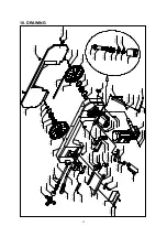
Loosen #20 bolts, rotate #19 Hex. cap bolt, so that the blade guide bushings vertically
position the blade in axis. Tighten #20 bolts until the blade secured. The front blade
guides must be positioned the nearest possible to the piece to be cut. Check every 3
months the existing tolerance between the blade guides, making sure that it does not
exceed the blade thickness of one tenth of a millimeter, so as to avoid inexactnesses
in the cut squaring. Periodically check with mounted blade that the blade guide
bearings rotate freely.
B. Lubrication of mobile parts of piece locking vice
Remove #93 jaw, withdraw #92 vice completely by lowering #86 lever. Clean and
grease the mobile parts of #98 counter-vice and 92 vice. If the vice slid difficult, adjust
#89 bolt. Lubricate the band guide devices regularly.
C. Cleaning of the coolant tank
The coolant tank can be cleaned by simply removing #148 bolts. Empty the coolant
from the tank and collect the coolant in a container for future disposal. Clean away the
shavings and the metallic powder, taking care not to scatter this over the machine
especially around the motor and the box containing the electrical equipment. Fill the
tank with the amount and liquid stated earlier.
D. Checking of bench lever functioning
Check rotation release-locking lever is working properly regularly. In the event of the
lever not locking correctly, loosen #137 grub screw, tighten #138 nut and fasten #137
grub screw again. Make sure that with the bench lever in right position, #117 rotating
arm which supports the bow can rotate freely.


