Operation Manual MUB-1
Model MUB-1
— 2 —
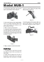
between the selected shaft and the Vise (#6)
and clamp it down as shown in Figure 1.
Figure 1
3. Put the Short Shaft (#9) into one of the
handle’s holes. Use the hole as close to the
bender as the material will permit.
4. Hold the material lightly with your thumb to
ensure parallel results (if desired).
5. Pull the handle in a clockwise direction for
a 1/4 turn. This should result in a 90degree
bender. If desired, you may insert the Stop
Pin (#16) at the appropriate hole for repetitive
bends. Typically, this will be the hole at the
front of the bender (furthest away from the
Vise Control Knob), second from the right as
shown in Figure 2.
Figure 2
6. Loosen the vise. Position the material so
that your bend is opposite the handle when it
is in the starting position. The straight part of
the material should be extending out towards
the handle; a slight amount of the bend should
be clamped when the vise is tightened.
workshop childproof. Use padlocks to prevent
any unintentional use of tools.
10. Assemble only according to these instructions.
Improper assembly can create hazards.
11. When tools are not in use, store them in a dry,
secure place out of the reach of children. Inspect
the tools prior to storage and before reuse.
12. Maintain product labels and nameplates.
These carry important safety information.
WARNING
The warnings, cautions, and instructions
discussed in this instruction manual cannot
cover all possible conditions or situations
that could occur. It must be understood
by the operator that common sense and
caution are factors which cannot be built
into this product, but must be used by the
operator.
OPERATING PROCEDURES
NOTE
The Universal Bender must be clamped to a
solid workbench or affixed in the T-slot of a
stable machine tool.
To Make Eyes and Centered Eyes:
1. Attach the Handle (#17) to the Working
Plate (#2) using the 1/2" Shaft (#10) with or
without the 1" Circle (#14), the 1/4" Shaft
(#11), or the 3/16" Shaft depending upon your
desired result. Secure the shaft with the Hex
Head Screw (#22). When you are standing
opposite the Vise Control Knob (#13), the
handle should be to your right and as far as
possible against the body of the bender.
2. Put the material you wish to bend in


