background image


8


4. ADJUSTMENTS : 


-  4.1 Switching on the machine : 


Turn on the machine with the main switch (Rep. a) located at the back of the machine.  
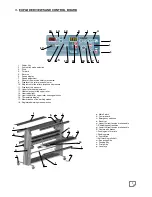
The control board lights up (light Rep 1). Press « power » (Rep.1). 


-  4.2 Temperature adjustment : 

 
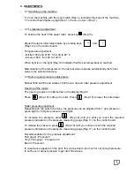
To activate the heat of the upper roller, press key       (Rep.13). 
 
 
Adjust the upper roller temperature by pressing keys               and         
(Rep.12) on the control board. 
 
Temperature adjustment  
- Mistral 1650 and 2100 : from 30 to 60° C  
- Arkane 1650 : from 40 to 140°C 
 
When light is on, the light (Rep.14) indicates that the set temperature is reached. 
 
Memorisation of the temperature : the last set value replaces automatically the former 
value in the selected memory.  
 

-  4.3 Roller nip and pressure adjustments : 

 
Mistral 1650 & 2100 and Arkane 1650 have a nip and roller pressure adjustment. 
 
Opening of the rollers : 
The opening is given in millemetres on the display (Rep.9). 
 
Press            (Rep.10) to lift up the roller. Press            (Rep.10) to lower the roller down.  
 
 
Roller pressure adjustment : 
Depending on the work to be done, the pressure can be adjusted from 1 (low pressure = 
green light) to 5 (higher pressure = red light). 
 
To increase the pressure, press       (Rep.10) until you until you reach the required 
pressure indicated on the pressure measuring gauge (Rep.11) on the control board. 
 
To release the pressure, press           (Rep.10) until you until you reach the required 
pressure indicated on the pressure measuring gauge (Rep.11) on the control board. 
 
Recommendation for the pressure adjustment : 
Thin paper : Pressure 5 
Vinyl, thick paper : Pressure 3/4 
Board : Pressure 1 
 
In case waves appears on the print, this can be due to too much or not enough pressure. 
In such event, adjust pressure to get rid of the waves. 


Summary of Contents for Arkane 1650

Page 1: ...1 USER S MANUAL Mistral 1650_Mistral 2100_Arkane 1650...

Page 2: ...on cannot be corrected consult your supplier Make sure that the series number and the date of purchase of your machine are to hand if you have to return the machine to the supplier Damage during trans...

Page 3: ...peed adjustment p 9 4 5 Forward and reverse p 9 4 6 Memories p 9 4 7 Foot switch p 10 4 8 Film tension adjustment p 10 5 HIGHLIGHTS OF THE MACHINE 5 1 Storage of film reels on the machine p 11 5 2 Fee...

Page 4: ...ould be installed so that you can easily access all parts of the machine and have enough free space around the machine 1 2 Unpacking the machine Remove the lid on top of the cardboard Tear off the car...

Page 5: ...is laminating machine close to water Leave a large enough working area behind the machine Do not spill water on the machine the supply lead or the electric socket Do not use the machine if the supply...

Page 6: ...one of these safety mechanisms is used the safety reset key Rep 8 flashes in red Correct the defect press on the safety reset key on the control panel Turn the machine off with the main switch Rep A w...

Page 7: ...r upper roller heating selection 16 Temperature display 17 Memorisation of the working modes 18 Registered working mode selection 17 10 7 8 16 14 12 13 11 6 9 5 3 4 2 1 18 15 3 EXPLODED VIEWS AND CONT...

Page 8: ...have a nip and roller pressure adjustment Opening of the rollers The opening is given in millemetres on the display Rep 9 Press Rep 10 to lift up the roller Press Rep 10 to lower the roller down Roll...

Page 9: ...set speed Stop to stop the machine press the Stop key rep 3 Alternatively you can also stop the machine by pressing on the footswitch if the footswitch mode is not activated foot switch light indicato...

Page 10: ...orward When the print is fed correctly and running through its lamination process press the forward key Rep 4 to run automatically b Stop function If the foot switch mode is not selected Rep 2 light o...

Page 11: ...or cleaning The tray is linked to a safety switch When in upper position the driving motor is shut off and the rollers cannot start However it is still possible to lift the roller up and down When tak...

Page 12: ...shaft for prints An unwinding shaft Rep I can be used to preserve your print on rolls from dust and damages It is meant for small rolls wounded onto 2 or 3 carton core This shaft can be position on t...

Page 13: ...file grips the carton mandrel To unload the media roll twist the mandrel to release it and slide it out 6 2 Loading a self blocking shaft on the machine The shaft holder on the right are built with a...

Page 14: ...taneously Lamination film Take up of the protection liner Double sided adhesive Single side lamination with double sided adhesive using 2 protection paper Lamination film Take up of the protection lin...

Page 15: ...ky side of the film should be facing outside the machine towards the user Refer to the winding way of the film roll to confirm the way the paper should go Install a shaft with a carton mandrel on posi...

Page 16: ...raduation Align this media in regards with the lamination film Help yourself with the graduations on the shafts Double side adhesive should go directly to the lamination film bypassing the separation...

Page 17: ...e with your cut vinyl 6 4 d Double side lamination encapsulation Install a film on the upper position 1 Install another lamination film roll on position 3 and centre it with the graduation Align this...

Page 18: ...nd keep the print on the top roller so that this one keep the roller shape and avoid folds Adjust the speed and press the forward key or the foot switch While the board is fed through the machine remo...

Page 19: ...lder shaft delivered with the machine This can be loaded on one of the film storage position Or on a self blocking shaft on position 4 Long print roll rewound on a 3 core mandrel can be loaded as a wa...

Page 20: ...d in accordance with the selected speed The rewinding speed is linked to the lamination speed and the laminated prints will be wound automatically on the mandrel Unloading the rewinding system When th...

Page 21: ...ight and tight at each corner For easier process to keep the print flat slide it under the paper guide in front of the roller Press forward on the control panel or on the foot switch to start Maintain...

Page 22: ...has been designed and built so that the noise caused by functioning is lower than 70 dB 8 CLEANING MAINTENANCE RECYCLING 8 1 Cleaning When What Action Immediately Ink on the rollers soap and water La...

Reviews: