


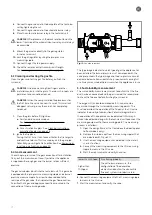
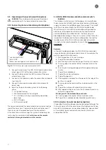

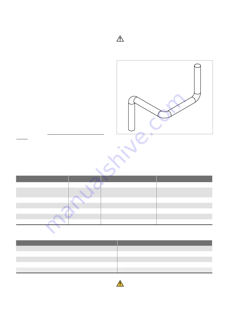
CAREFUL! Many elbows and/or horizontally-mounted
components of the concentric flue duct system can
create substantial resistance. The flame pattern can vary
considerably because the combustion air cannot easily
reach the gas fire.
Fig. 3: Flue duct components
4. Preparation
The upcoming sections provide preparatory information prior to
installation of the gas fire:
- Preliminary work with the help of a scale drawing
- Chimney calculation
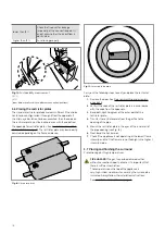
- Check the gas fire and determine the location of the
technical unit
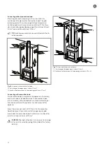
4.1 Preliminary work with the help of a scale drawing
You can use to your advantage a scale drawing prior to and during
the placing of the concentric flue duct system and the gas fire.
Scale drawings are available on the http://www.kalfire.com/en/
fireplaces website. Select the correct gas fire type here. Once you
have made your choice, a page will open on which you will find
“technical information”. The subject “documents” with the scale
drawing of the gas fire can be found there too.
4.2 Chimney calculation
Calculate the concentric flue duct system with the values of the
chimney calculation or make a choice from the configurations in
the appendices. See: flue duct configurations 1 through 6 on
page 35. A chimney calculation is made for the roof pass-through
and the wall pass-through. The chimney calculation is suitable
for gas types G20, G25 and G30. Kalfire cannot guarantee proper
operation of the fireplace if your configuration does not comply
to the chimney calculation.
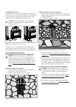
A
A
B
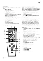
Table 1: Calculation values chimney calculation
Example of chimney calculation
Result:9 + 1 - 2 - 4 - 4 = 0. (This chimney calculation is not
acceptable, it must be at least 0.5)
WARNING: the sum of all calculation values must be
higher than 0.5. At a value lower than 0.5, the gas fire
will not function according to standard EN613. Deviating
configurations can be presented to Kalfire for written
approval.
Components
Calculation values
Maximum permitted Kalfire G
Maximum permitted Kalfire GP
First vertical metre
+9
Second metre and subsequent
vertical metres
+1
23 metres
11 metres
1 metre horizontal pipe
-1
7 metres
5 metres
1 90° vertical elbow (A)
-2
3 units
3 units
1 45° vertical elbow
-1
6 units
6 units
1 90° horizontal elbow (B)
-4
2 units
2 units
1 45° horizontal elbow
-2
4 units
4 units
Used parts
Calculation values
1x 1st vertical metre
+9
1x 2nd vertical metre
+1
2x metre horizontal pipe
-2
2x 90* vertical elbow (A)
-4
1x 90* horizontal elbow (B)
-4
12
Summary of Contents for G Series
Page 1: ...Installation instructions BALANCED FLUE GAS FIRES DON T COMPROMISE EN...
Page 2: ......
Page 4: ...4...
Page 43: ...1 4 6 7 5 2 3 43...
Page 45: ...1 3 2 5 4 6 7 8 8 7 45...
Page 47: ...1 9 4 7 3 8 5 6 2 10 47...
Page 49: ...5 1 2 3 7 4 6 8 10 9 9 49...
Page 51: ...4 5 3 6 1 1 51...
Page 52: ...7 2 7 7 2 2 8 52...
Page 54: ...4 5 2 1 1 3 54...
Page 55: ...9 8 6 7 1 55...
Page 57: ...5 6 7 8 3 2 2 1 57...
Page 58: ...9 4 4 8 58...
Page 60: ...5 2 9 6 2 1 4 3 60...
Page 61: ...7 7 10 11 8 61...
Page 63: ...1 7 7 3 4 6 2 7 63...
Page 64: ...2 4 4 5 5 8 64...
Page 66: ...7 4 5 6 1 8 9 66...
Page 67: ...3 3 11 2 10 10 12 67...
Page 69: ...1 2 6 6 8 8 9 7 7 4 With gas type G30 log 4 to be placed at extreme right 3 4 5 11 69...
Page 72: ...10 2 1 9 11 3 3 4 5 5 7 6 72...
Page 73: ...13 12 12 12 8 73...
Page 76: ...3 1 6 5 4 2 13 76...
Page 77: ...14 7 10 11 8 12 12 Other side Divide 15 cryptonite and 16 ash 77...
Page 80: ...3 4 5 7 1 3 4 5 6 1 4 5 1 3 4 1 3 2 1 2 3 1 3 1 2 4 5 1 6 2 6 7 14 12 11 11 3 80...
Page 81: ...3 4 5 7 8 1 3 4 7 9 10 8 3 4 5 6 7 8 1 3 4 5 6 7 8 1 3 4 5 6 7 1 9 10 8 15 13 81...
Page 84: ...4 3 5 2 3 4 5 1 2 3 4 5 1 1 2 3 4 1 1 2 1 1 1 2 1 1 1 1 1 2 3 4 5 6 6 1 1 1 14 11 84...
Page 94: ...94...
Page 95: ...95...
Page 96: ...Gelo rveldweg 21 5951 DH Belfeld info kalfire nl KALFIRE COM DON T COMPROMISE REF V01 2019 EN...


