


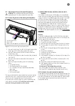
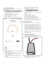


5.2.3 Continuous rear wall finishing (option)
When opted for a continuous real wall finishing, the following
steps should be carried out:
1. Determine the side to which the rear wall is to be continued.
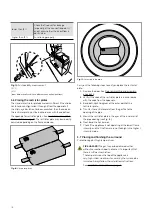
2. Remove the four nuts as depicted in the figure.
Fig. 10: Removing the strip
3. Unscrew the upper and lower nuts.
4. Remove the steel vertical strip.
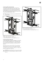
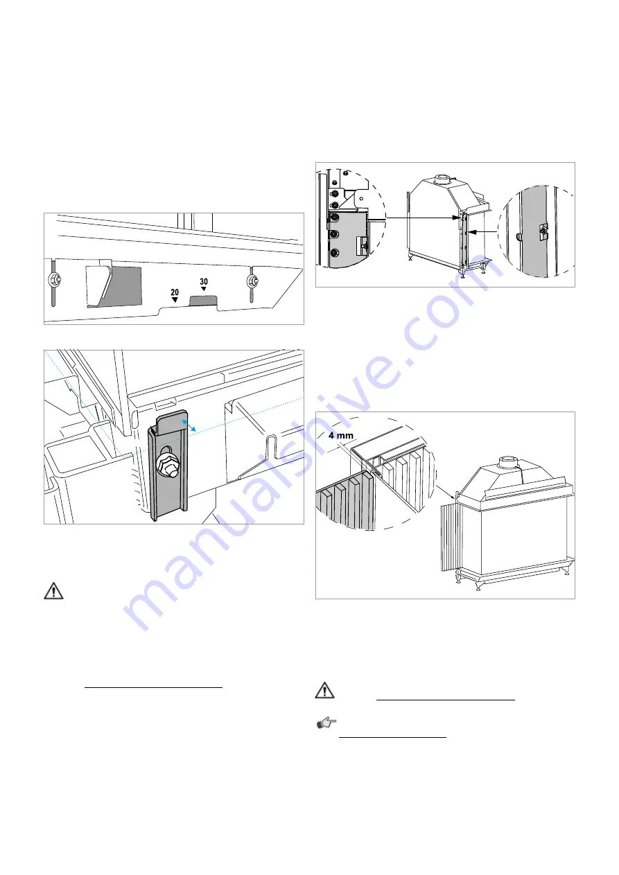
5. Place the panel (ceramic glass or design) that you wish to
continue outside of the fireplace in the correct position.
6. Always leave 4 mm space between the panel and the
glass frame, in order to keep it accessible for service
requirements.
Fig. 11: Space between panel and fireplace (4 mm)
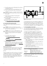
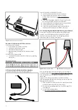
5.2.4 Connecting the gas fire
This task describes how to connect the technical unit and the gas
fire.
CAREFUL! Do not directly expose the technical unit to
heat. See Installation Instructions on page 8 .
REMARK: Use the wiring diagram when connecting. See
Wiring diagram on page 86.
1. Connect the flexible gas hose to the side of the gas fire.
2. Check the connection for gas leakage.
3. Assemble the 24V power supply cable.
4. Connect the white plug to the ionisation cable.
5. Place the ionisation cable (covered by the black surround at
the end).
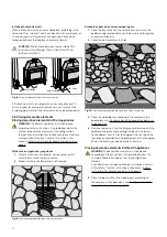
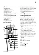
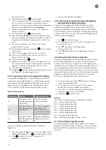
5.2.2 Adjusting the stone support
The gas fire is equipped with stone support, so tiles or other
plateau-finishing materials can be supported to the side of the
fireplace.
The stone support can be adjusted without using steps over a 30
mm distance. The stone support is equipped with an indicator
for a stone thickness of 20 mm to 30 mm, as depicted. The stone
support can also be removed as one.
Fig. 8: Stone thickness indicator
Fig. 9: Glass support (corner and three-sided appliances only)
Carry out the following steps to adjust the stone support;
CAREFUL! While adjusting the stone support, the glass
support to the left and right of the appliance cannot be
removed.
1. Unscrew the nuts at the bottom end of the assembly strip.
2. Set the desired height.
3. Tighten the screws and place the stones.
4. Leave a minimum of 4 mm between the stone and the glass.
See Installation Instructions on page 8.
5. At the front, leave a minimum of 1 mm of space between the
glass support and the finishing. Prevent excessive tension
on the glass caused by the glass support as a result of heat
expansion.
1 mm
16
Summary of Contents for G Series
Page 1: ...Installation instructions BALANCED FLUE GAS FIRES DON T COMPROMISE EN...
Page 2: ......
Page 4: ...4...
Page 43: ...1 4 6 7 5 2 3 43...
Page 45: ...1 3 2 5 4 6 7 8 8 7 45...
Page 47: ...1 9 4 7 3 8 5 6 2 10 47...
Page 49: ...5 1 2 3 7 4 6 8 10 9 9 49...
Page 51: ...4 5 3 6 1 1 51...
Page 52: ...7 2 7 7 2 2 8 52...
Page 54: ...4 5 2 1 1 3 54...
Page 55: ...9 8 6 7 1 55...
Page 57: ...5 6 7 8 3 2 2 1 57...
Page 58: ...9 4 4 8 58...
Page 60: ...5 2 9 6 2 1 4 3 60...
Page 61: ...7 7 10 11 8 61...
Page 63: ...1 7 7 3 4 6 2 7 63...
Page 64: ...2 4 4 5 5 8 64...
Page 66: ...7 4 5 6 1 8 9 66...
Page 67: ...3 3 11 2 10 10 12 67...
Page 69: ...1 2 6 6 8 8 9 7 7 4 With gas type G30 log 4 to be placed at extreme right 3 4 5 11 69...
Page 72: ...10 2 1 9 11 3 3 4 5 5 7 6 72...
Page 73: ...13 12 12 12 8 73...
Page 76: ...3 1 6 5 4 2 13 76...
Page 77: ...14 7 10 11 8 12 12 Other side Divide 15 cryptonite and 16 ash 77...
Page 80: ...3 4 5 7 1 3 4 5 6 1 4 5 1 3 4 1 3 2 1 2 3 1 3 1 2 4 5 1 6 2 6 7 14 12 11 11 3 80...
Page 81: ...3 4 5 7 8 1 3 4 7 9 10 8 3 4 5 6 7 8 1 3 4 5 6 7 8 1 3 4 5 6 7 1 9 10 8 15 13 81...
Page 84: ...4 3 5 2 3 4 5 1 2 3 4 5 1 1 2 3 4 1 1 2 1 1 1 2 1 1 1 1 1 2 3 4 5 6 6 1 1 1 14 11 84...
Page 94: ...94...
Page 95: ...95...
Page 96: ...Gelo rveldweg 21 5951 DH Belfeld info kalfire nl KALFIRE COM DON T COMPROMISE REF V01 2019 EN...


