


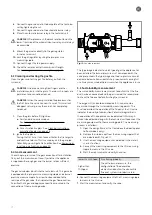
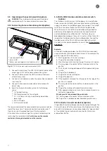


6. Connect the ground wire to the back plate of the technical
unit by tightening the nut.
7. Connect the ground wire to the automatic burner relay.
8. Place the automatic burner relay in the technical unit.
CAREFUL! After placement, the black reset button on the
lower-front side of the automatic burner relay must always
be accessible.
9. Mount the gas valve directly to the gas regulator
in the technical unit.
10. Vent the gas regulator by using the pre-pressure
measuring nipple.
11. Connect the gas fire to a power supply.
12. Check the remote control transmission strength.
See: Checking transmission strength on page 24.
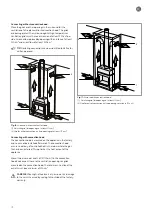
5.3 Cleaning and testing the gas fire
Clean the glass and test the gas fire before you finish the
surround.
CAREFUL! Grease emanating from fingers or other
materials can burn into the glass. These burnt-in spots are
permanent and cannot be cleaned.
CAREFUL! When the newly-installed fireplace burns for
the first time, the varnish can emit a smell. This smell will
disappear naturally, once the varnish has completely
hardened.
1. Clean the glass before first ignition.
a. For standard ceramic windows.
See: Cleaning the (standard) ceramic windows
on page 28.
b. For anti-reflective glass. See: Cleaning instructions
anti-reflective glass on page 28.
2. Ignite the fireplace
During the first time, it can take a while for the fire to ignite
and continue to burn. This is caused by air in the gas pipe.
Potentially, you will get a 08A notification. See Removing or
resetting a malfunction on page 30.
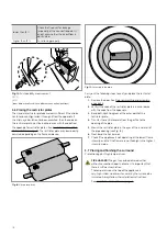
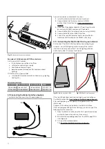
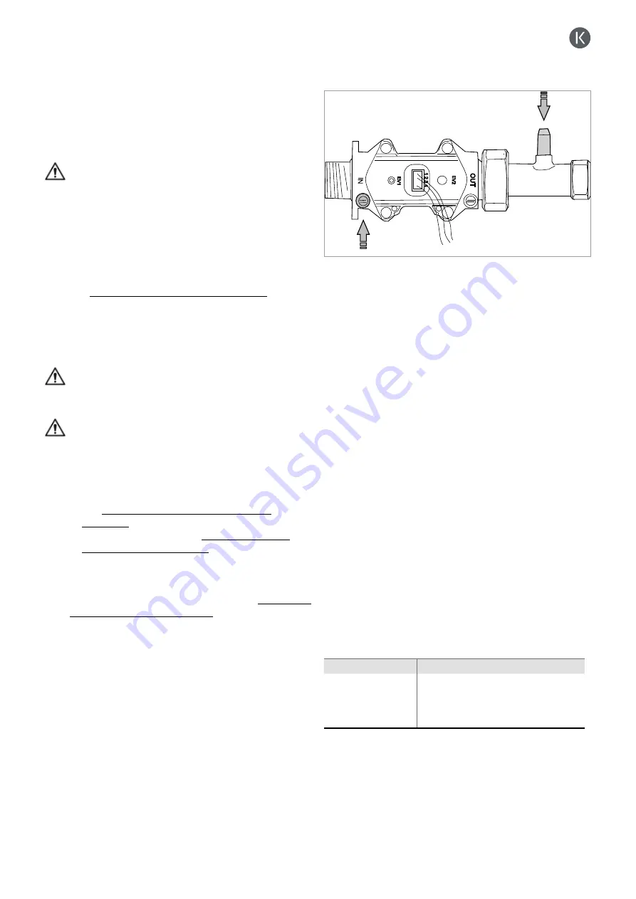
5.4 Gas measurement
Check the pre-pressure of the gas connection after installation.
Carry out this measurement to verify whether the appliance
is supplied with enough gas and the burner retains sufficient
pressure.
The gas valve below is built into the technical unit. This gas valve
is equipped with a pre-pressure measuring nipple and a burner
pressure measure nipple. An arrow has been added to the
rear side of the gas valve, that indicates the gas flow direction.
An orifice that is gas and appliance specific is mounted in the
connection of the measuring device.
Fig. 12: Gas measurement
The type image indicates to which type of gas the appliance has
been installed. The burner pressure must correspond with the
value presented in the type image and the pre-pressure cannot
decrease below nation-wide statutory requirements during full
use. Always measure both pressures when the appliance is in use.
5.5 Sustainability measurement
The sustainability measurement serves to confirm that the flue
duct has been connected and the gas is sealed. We recommend
to check the flue duct before finishing the surround.
The oxygen (O
²
) and carbon monoxide (CO) values can be
measured through the sustainability measuring points. The
O
²
value describes the operation of the flue duct, the CO value
indicates the quality of combustion. Potential irregularities in
the operation of the appliance can be detected in this way. A
silicon tube delivered along with the technical unit to connect the
measuring equipment to the measuring points. The measuring
process is as follows:
1. Open the design frame at the front above the door (applies
to front models only).
2. Remove the rubber caps from the measuring nipples that
are indicated with O
²
and CO.
3. Use the measuring equipment as indicated in the meter’s
user instructions.
4. Connect the measuring equipment to the CO measuring
nipple to measure the CO value.
5. Start the measurement and verify the values;
lower than 1000ppm Functioning properly.
higher than
1000ppm
Check the burner pressure, the
configuration of the decorative
elements and confirm the concentric
flue duct system is not obstructed.
6. Connect the measuring equipment to the O
²
measuring nipple
to measure the O
²
value.
7. Start the measurement and verify the value;
17
Summary of Contents for G Series
Page 1: ...Installation instructions BALANCED FLUE GAS FIRES DON T COMPROMISE EN...
Page 2: ......
Page 4: ...4...
Page 43: ...1 4 6 7 5 2 3 43...
Page 45: ...1 3 2 5 4 6 7 8 8 7 45...
Page 47: ...1 9 4 7 3 8 5 6 2 10 47...
Page 49: ...5 1 2 3 7 4 6 8 10 9 9 49...
Page 51: ...4 5 3 6 1 1 51...
Page 52: ...7 2 7 7 2 2 8 52...
Page 54: ...4 5 2 1 1 3 54...
Page 55: ...9 8 6 7 1 55...
Page 57: ...5 6 7 8 3 2 2 1 57...
Page 58: ...9 4 4 8 58...
Page 60: ...5 2 9 6 2 1 4 3 60...
Page 61: ...7 7 10 11 8 61...
Page 63: ...1 7 7 3 4 6 2 7 63...
Page 64: ...2 4 4 5 5 8 64...
Page 66: ...7 4 5 6 1 8 9 66...
Page 67: ...3 3 11 2 10 10 12 67...
Page 69: ...1 2 6 6 8 8 9 7 7 4 With gas type G30 log 4 to be placed at extreme right 3 4 5 11 69...
Page 72: ...10 2 1 9 11 3 3 4 5 5 7 6 72...
Page 73: ...13 12 12 12 8 73...
Page 76: ...3 1 6 5 4 2 13 76...
Page 77: ...14 7 10 11 8 12 12 Other side Divide 15 cryptonite and 16 ash 77...
Page 80: ...3 4 5 7 1 3 4 5 6 1 4 5 1 3 4 1 3 2 1 2 3 1 3 1 2 4 5 1 6 2 6 7 14 12 11 11 3 80...
Page 81: ...3 4 5 7 8 1 3 4 7 9 10 8 3 4 5 6 7 8 1 3 4 5 6 7 8 1 3 4 5 6 7 1 9 10 8 15 13 81...
Page 84: ...4 3 5 2 3 4 5 1 2 3 4 5 1 1 2 3 4 1 1 2 1 1 1 2 1 1 1 1 1 2 3 4 5 6 6 1 1 1 14 11 84...
Page 94: ...94...
Page 95: ...95...
Page 96: ...Gelo rveldweg 21 5951 DH Belfeld info kalfire nl KALFIRE COM DON T COMPROMISE REF V01 2019 EN...


