


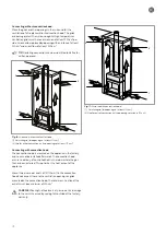
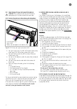
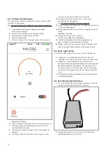


Connect the cables as indicated in the visual.
1. Install the iMatch interface in the technical unit.
2. Connect cable A to the burner control (HDIMS)
and the iMatch interface. See: the wiring diagram on
page 86.
3. Disconnect the adaptor cable (24 V) from the automatic
burner relay (HDIMS) and connect it to cable B.
4. Connect cable B1 to the automatic burner relay (HDIMS).
5. Connect cable B2 to the iMatch interface.
6. Check if the red LED indicator lights up on the iMatch
interface and if the lamp on the HDIMS is flashing.
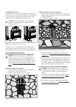
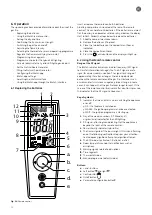
5.11.1 Connecting the iMatch interface to your network
First connect the iMatch interface before connecting to your
network. The red LED lighting will flash slowly if the iMatch
interface is correctly connected. The LED lighting will be on
continuously after it has been switched on.
Fig. 24: iMatch interface LEDs Fig. 25: iMatch interface reset
If the red LED lighting is continuously alight, you can configure
the iMatch connection. See: Configure the iMatch app on page 26.
After configuration you can operate the appliance with the
iMatch app,
the green LED will be on and visible in the iMatch interface.
If the red and green LED lights are flashing, you can carry out the
following steps to reconnect;
1. Place the iMatch interface and the Wi-Fi point closer to one
another to reduce the distance (if necessary).
2. Erase the corresponding room from the iMatch app (if this
is configured).
3. Carry out the reset procedure.
See: Resetting the iMatch interface on page 26.
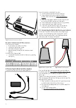
B1
B2
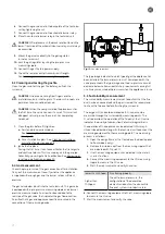
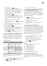
Fig. 22: Connector for external devices
Examples of AUX devices and OPEN contacts are:
‘AUX’ devices (AUX enable):
•
fan to improve convection air outflow.
•
safety valve control in gas supply
•
illumination of indicator lights
•
powered up electrical devices (for example: indirect
lighting).
‘OPEN’ contacts (Open enable)
•
switched off / deactivated electrical devices (e.g. lighting,
heating etc.).
Schematic overview:
Connection Fire switched on Fire switched off MAX
Open enable Open contact
Closed contact
250 VAC / 5A
AUX enable Closed contact
Open contact
250 VAC / 5A
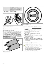
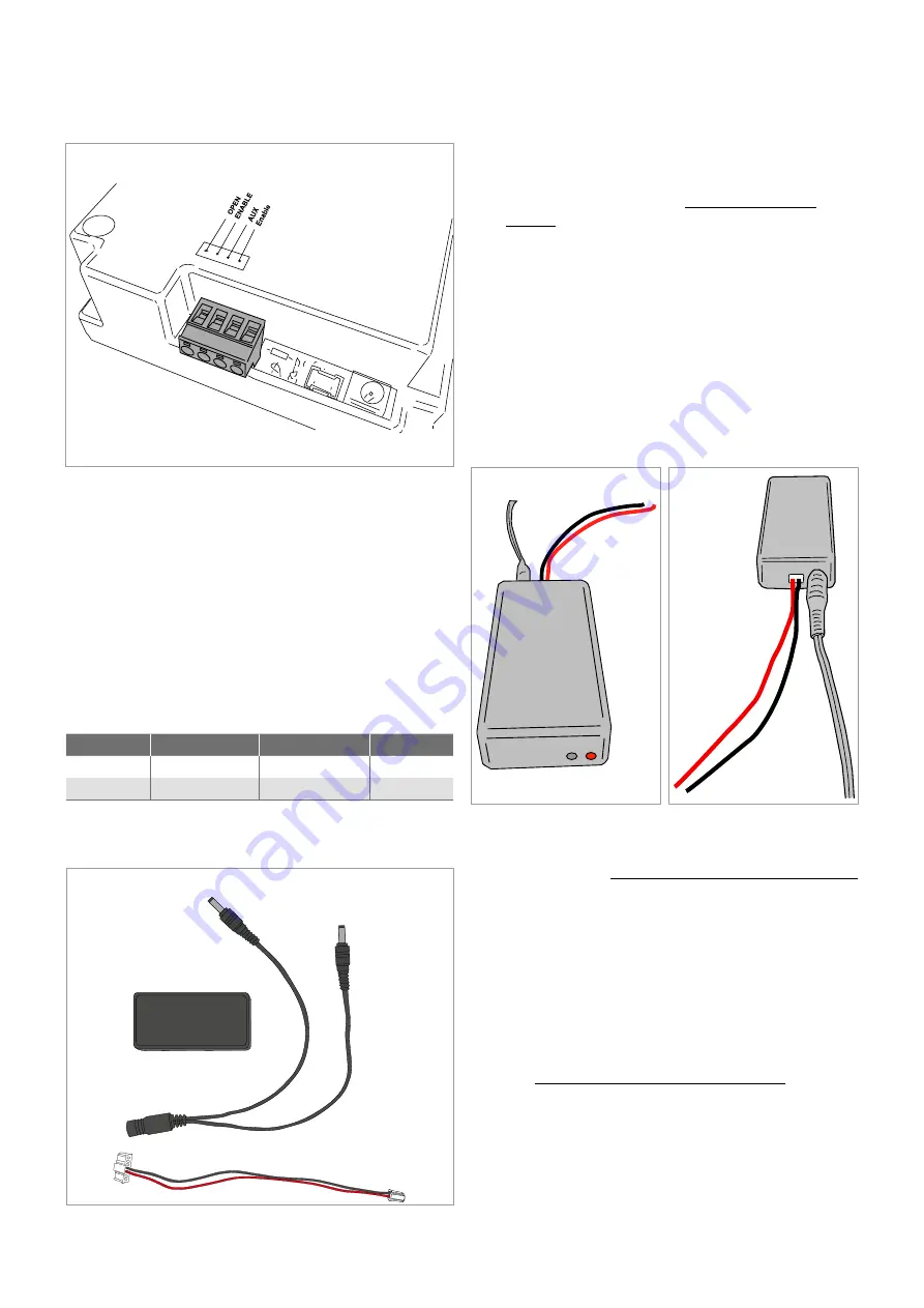
5.11 Connecting the iMatch interface (option)
The iMatch interface consists of three components.
Fig. 23: iMatch interface
22
Summary of Contents for G Series
Page 1: ...Installation instructions BALANCED FLUE GAS FIRES DON T COMPROMISE EN...
Page 2: ......
Page 4: ...4...
Page 43: ...1 4 6 7 5 2 3 43...
Page 45: ...1 3 2 5 4 6 7 8 8 7 45...
Page 47: ...1 9 4 7 3 8 5 6 2 10 47...
Page 49: ...5 1 2 3 7 4 6 8 10 9 9 49...
Page 51: ...4 5 3 6 1 1 51...
Page 52: ...7 2 7 7 2 2 8 52...
Page 54: ...4 5 2 1 1 3 54...
Page 55: ...9 8 6 7 1 55...
Page 57: ...5 6 7 8 3 2 2 1 57...
Page 58: ...9 4 4 8 58...
Page 60: ...5 2 9 6 2 1 4 3 60...
Page 61: ...7 7 10 11 8 61...
Page 63: ...1 7 7 3 4 6 2 7 63...
Page 64: ...2 4 4 5 5 8 64...
Page 66: ...7 4 5 6 1 8 9 66...
Page 67: ...3 3 11 2 10 10 12 67...
Page 69: ...1 2 6 6 8 8 9 7 7 4 With gas type G30 log 4 to be placed at extreme right 3 4 5 11 69...
Page 72: ...10 2 1 9 11 3 3 4 5 5 7 6 72...
Page 73: ...13 12 12 12 8 73...
Page 76: ...3 1 6 5 4 2 13 76...
Page 77: ...14 7 10 11 8 12 12 Other side Divide 15 cryptonite and 16 ash 77...
Page 80: ...3 4 5 7 1 3 4 5 6 1 4 5 1 3 4 1 3 2 1 2 3 1 3 1 2 4 5 1 6 2 6 7 14 12 11 11 3 80...
Page 81: ...3 4 5 7 8 1 3 4 7 9 10 8 3 4 5 6 7 8 1 3 4 5 6 7 8 1 3 4 5 6 7 1 9 10 8 15 13 81...
Page 84: ...4 3 5 2 3 4 5 1 2 3 4 5 1 1 2 3 4 1 1 2 1 1 1 2 1 1 1 1 1 2 3 4 5 6 6 1 1 1 14 11 84...
Page 94: ...94...
Page 95: ...95...
Page 96: ...Gelo rveldweg 21 5951 DH Belfeld info kalfire nl KALFIRE COM DON T COMPROMISE REF V01 2019 EN...


