background image

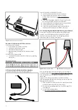
approved fitter and is not supplied with the appliance. Power 
supply and required electrical power:
  1.  For all appliances without hybrid LED lighting: 230V/22W. 
 2.   For all appliances with hybrid LED lighting and Natural 

Spark Generator: 230V/40W. 


 WARNING The gas fire needs a permanent power supply. 
Errors recorded earlier are lost during any interruption to 
power supply. Regular interruption of the power supply 
impacts the safety mechanisms, whereby hazardous 
situations can arise.

2.3   Installation instructions

The following conditions must be adhered to during installation:


 WARNING Ensure sufficient ventilation in the area in 
which the gas fire is to be installed. The installation area is 
sufficiently ventilated if: 

The nominal power of the appliance 

in kilowatt / content of the installation area in cubic metres 
is less than 35.

    •    

Reference is made to both national and local provisions 
in force to determine a safe distance from the wall 
against which the appliance is mounted and the adjacent 
walls, roof ducts and windows.

   •

    Only non-flammable materials should be used during 

installation of the gas fire.

   •

   Ensure sufficient ventilation in the area in which the gas 

fire is to be installed. The installation area is sufficiently 
ventilated if: 

The nominal power of the appliance in 

kilowatt / content of the installation area in cubic metres 
is less than 35.

   •

   Reference is made to both national and local legislation 

in force to determine a safe distance from the wall pass-
through against which the appliance is mounted and the 
adjacent walls, roof ducts and windows.


   •

   Only non-flammable materials should be used during 

installation of the gas fire.


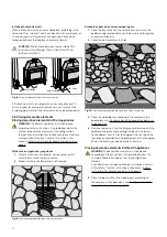
 WARNING No flammable materials may be used close 
to the concentric flue duct system. High external wall 
temperatures up to approximately 150°C form a burn 
hazard. Keep a minimum distance of 80 mm from 
flammable materials.

   •

   The floor on which the appliance is mounted must 

consist of heat-resistant material. Should that not be 
the case, then no flammable material may be placed 
under the appliance. This also goes for the walls behind 
and adjacent to the appliance and the ceiling.
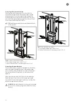
  

    The temperature of the wall and/or walls against which 

the appliance is placed may not exceed 85°C. Before 
placing the appliance, these walls must be insulated with 
fire-resistant material. This fire-resistant material should 
be insulated with, for example, a 3-cm calcium-silicate 
plate (0.07 W/m.K). A gap should also be left between 
the fireplace and the insulated fire-resistant material.

    •  

The materials used for the surround of the gas fire need 
to be heat resistant and fire-free. The gas fire may under 
no circumstances
be insulated. Material, stucco and 

2. Safety

The following sections provide safety information about the gas 
fire:
  -   Safety related to installation 
  -   Gas and electrical units already installed 
  -   Installation regulations 
  -   Safety regulations for decorative elements 
  -   Safety related to use 
  -   Three safety measures for the gas fire 

2.1  Safety related to installation

Installation of the gas fire requires diligent pursuit of procedures. 
During installation, please adhere to the regulations that apply to 
safety and health in your country (the Working Conditions Act, for 
example).

General installation instructions:

 •

   The procedures described may only be carried out by 

authorised technical professionals.

 •

   Follow the installation procedures diligently to avoid 

damage and accidents.

 •

   Use adequate protection resources during installation.

 •

   Ensure that local circumstances such as gas pressure and 

the type of gas are consistent with the information on the 
data identification plate of the gas fire.

 •

   Only install a gas fire in an area that has sufficient ventilation 

in compliance with the standards in force.

 •

   Always conduct a chimney calculation, as indicated in the 

Chimney Calculation.

 •

   Always make use of a concentric flue duct system that 

complies with the approval conditions of your gas fire.

 •

  Adhere to the installation regulations as stated. 

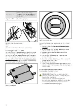
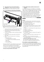
2.2   Gas and electrical units already installed

Concentric flue duct system confirmation
The gas piping and gas control valve to the fireplace need to be 
installed by an authorised fitter and are not supplied with the 
appliance. The diameter of the gas piping must be determined for 
each appliance in compliance with the directives in force:

 •

   NEN 1078 and NPR 3378 apply to The Netherlands.

 •

   NBN D51-003 (chimney connection and gas connection) 

applies to Belgium.

 •

   Arbeitsblatt G600 DVGW-TRGI applies to Germany.

Gas specification confirmation
Check to confirm that the gas specifications comply with the 
installation. The data identification plate indicates the gas 
type and gas pressure that is suitable for the appliance. The 
identification plate is located on the inside door of the technical 
unit and at the rear right of the bottom of the appliance. Kalfire 
should be consulted if you wish to use a gas fire together with 
another gas type.

Electrical installation confirmation
The electrical installation to the gas fire must be installed by an 

8

Summary of Contents for G Series

Page 1: ...Installation instructions BALANCED FLUE GAS FIRES DON T COMPROMISE EN...

Page 2: ......

Page 3: ...37S G160 41F G165 37C G170 37S for gas type G20 G25 and G30 Balanced flue gas fires Kalfire GP GP60 59F GP65 55C GP70 55S GP60 79F GP65 75C GP70 75S GP75 59F GP80 55C GP85 55S GP80 54T GP85 50R GP105...

Page 4: ...4...

Page 5: ...corative elements Kalfire GP80 54T and GP85 50R series 74 A 6 14 Placing decorative elements Kalfire G105 59 series 78 A 6 15 Placing decorative elements Kalfire G105 79 series 82 A 7 Wiring diagram 8...

Page 6: ...he original document Disclaimer All rights reserved No part of this manual may be copied distributed or translated into other languages in full or in part without the prior written permission of Kalfi...

Page 7: ...d by neglect improper use and or gross negligence 9 If the repair or delivery of individual parts be carried out by another manufacturer or by a professional technical fitter who has not been approved...

Page 8: ...te 0 07 W m K A gap should also be left between the fireplace and the insulated fire resistant material The materials used for the surround of the gas fire need to be heat resistant and fire free The...

Page 9: ...azard WARNING Make sure that flammable materials such as curtains and furniture are at least 100 cm from the fireplace If a fireguard is used this distance must be at least 40 cm wallpaper with which...

Page 10: ...ion chamber to the floor be smaller than 10 cm a heat resistant fireguard floor plate larger than 30 cm or a stone should be placed Danger of combustion FIRE HAZARD Do not touch the appliance The gas...

Page 11: ...ontrolled by the iMatch App on a smartphone or tablet This is only possible if the gas fire is equipped with the optional iMatch interface that serves as the receiver 3 Description The following secti...

Page 12: ...e from the configurations in the appendices See flue duct configurations 1 through 6 on page 35 A chimney calculation is made for the roof pass through and the wall pass through The chimney calculatio...

Page 13: ...e disconnected the following steps should be observed 1 Remove the automatic burner relay from the technical unit 2 Disconnect the earth wire on the automatic burner relay 3 Unscrew the bolt connected...

Page 14: ...describes technical unit connection and the gas supply Cleaning and testing the gas fire Gas measurement Check the pre pressure of the gas connection after installation Carry out this measurement to...

Page 15: ...and assemble the gas fire 1 Place the front glass in the appliance 2 Unscrew two bolts A from each support leg 3 To ensure that the support legs are on the desired height you might have to saw the to...

Page 16: ...power supply cable 4 Connect the white plug to the ionisation cable 5 Place the ionisation cable covered by the black surround at the end 5 2 2 Adjusting the stone support The gas fire is equipped wi...

Page 17: ...e is equipped with a pre pressure measuring nipple and a burner pressure measure nipple An arrow has been added to the rear side of the gas valve that indicates the gas flow direction An orifice that...

Page 18: ...n all cases it is important that there is sufficient ventilation The temperature on the top of the appliance is very high Under no circumstances may the surround be insulated Always follow the install...

Page 19: ...75 cm Connecting with convection hood The convection hood is mounted on the appliance in the factory and so cannot be installed afterwards The convection hood ensures a delivery of controlled heat in...

Page 20: ...nfiguration of the decorative elements on page 42 85 Installing the technical unit Place the technical unit in an accessible place preferably in the side wall of the surround Take the choice of materi...

Page 21: ...active and the remote control will display the notification 04F The flame stays in a blocked position so long as the switch is inactive When the switch is operated it will open and the flame will be...

Page 22: ...pp on page 26 After configuration you can operate the appliance with the iMatch app the green LED will be on and visible in the iMatch interface If the red and green LED lights are flashing you can ca...

Page 23: ...rting up 2 Day of the week in numbers 1 7 Monday is 1 a glow lamp Indicator for the LED lighting 3 RF signal a flashing icon indicating that the appliance is beyond the reach of the remote control 4 f...

Page 24: ...ts to flash in the top left hand corner of the display 4 Press the right button to display TCOM temperature comfort TCOM indicates the maximum temperature during all set time segments 5 Set the desire...

Page 25: ...elivery Use the instruction delivered with bthe new powder for refilling the Natural Spark Generator increments of 0 5 C 6 Confirm by pressing the centre button 7 TECO temperature ECO will now appear...

Page 26: ...replace Change the name of the room s present Select the room you want to change In the screen that appears next you are able to change the name 3 Wizard click on Wizard and follow the instruction to...

Page 27: ...ill start at 100 flame intensity 2 Setting the flame intensity Press and hold down the black dot Move your finger over the circle to set the flame intensity The percentage will increase and decrease w...

Page 28: ...roleum based solvents solvents scouring powders abrasive materials steel wool scrubbing or scouring pads scrapers razor blades paper ceramic stove cleaners Aggressive cleaning materials 7 Maintenance...

Page 29: ...by moving the handles down Twist the metal cover strips step 1 back into its original position by using the protruding lip at the upper side of the strip 7 1 4 Door dismantling and assembly front and...

Page 30: ...the automatic burner relay are tested The fireplace is automatically switched off and stays down until it is turned on again manually 7 2 1 Removing or resetting a malfunction The automatic burner rel...

Page 31: ...The yellow light will start flashing rapidly now 7 Immediately within 10 seconds press and hold it down until the word LINK starts flashing on the display 8 Wait until LINK 1 appears and release 9 Pre...

Page 32: ...side the technical unit See Wiring diagram on page 86 3 Check if there is sufficient 24V D C power supply 4 Check the ignition cable for damages and check the connection with the burner 5 Check the HD...

Page 33: ...e technical unit or place a Wi Fi repeater You have not entered the Wi Fi settings correctly in the app Check the Wi Fi settings Erase the added room from the app Reset the iMatch interface and try ag...

Page 34: ...he gas fire Flue duct configurations 1 to 6 Flue duct configurations G20 25 Flue duct configurations G30 Product card Restrictor plates G20 G25 and G30 Configuration decorative elements Wiring diagram...

Page 35: ...ion 4b reducerduct with roof pass through Configuration 5a diagonal duct with roof pass through Configuration 5b diagonal duct with rejuvenation and roof pass through Configuration 5c rejuvenation dia...

Page 36: ...A 2 Flue duct configurations G20 G25 The various flue pipe configurations are indicated in configuration 1 through 6 See Flue duct configurations 1 through 6 36...

Page 37: ...ical elbow Horizontal section max m 5 5 5 5 5 3 3 3 3 3 3 90 vertical elbow Connector 130 200 100 150 C Vertical 100 150 min 1 m Roof pass through B Remove the ceiling plate Configuration 4b 1st metre...

Page 38: ...A 3 Flue duct configurations G30 The various flue pipe configurations are indicated in configuration 1 through 6 See flue duct configurations 1 through 6 38...

Page 39: ...5 3 3 3 3 3 90 vertical elbow Connector 130 200 100 150 C Vertical 100 150 min 1 m Roof pass through B Remove the ceiling plate Configuration 4b 1st metre vertical min 0 5 m 90 vertical elbow Horizon...

Page 40: ...C 11 3 kW n a 79 82 0 79 6 Kalfire GP60 59F Kalfire GP65 55C Kalfire GP70 55S G25 D 6 2 kW n a 72 76 1 62 7 Kalfire GP60 59F Kalfire GP65 55C Kalfire GP70 55S G20 D 6 1 kW n a 72 76 0 66 7 Kalfire GP6...

Page 41: ...ounted below this value Appliances If the result of a chimney calculation is more than 5 5 mount the restrictor plate below G20 G25 G30 G60 48F G65 44C G70 44S 50 45 35 G80 48F G85 44C G90 44S 71 68 5...

Page 42: ...ctions It is prohibited to alter the number of decorative elements or the configuration thereof Such alterations can lead to hazardous situations with regard to fire safety Take the instructions into...

Page 43: ...1 4 6 7 5 2 3 43...

Page 44: ...alter the number of decorative elements or the configuration thereof Such alterations can lead to hazardous situations with regard to fire safety Take the instructions into account Safety instructions...

Page 45: ...1 3 2 5 4 6 7 8 8 7 45...

Page 46: ...e number of decorative elements or the configuration thereof Such alterations can lead to hazardous situations with regard to fire safety Take the instructions into account Safety instructions for dec...

Page 47: ...1 9 4 7 3 8 5 6 2 10 47...

Page 48: ...r of decorative elements or the configuration thereof Such alterations can lead to hazardous situations with regard to fire safety Take the instructions into account Safety instructions for decorative...

Page 49: ...5 1 2 3 7 4 6 8 10 9 9 49...

Page 50: ...alter the number of decorative elements or the configuration thereof Such alterations can lead to hazardous situations with regard to fire safety Take the instructions into account Safety instructions...

Page 51: ...4 5 3 6 1 1 51...

Page 52: ...7 2 7 7 2 2 8 52...

Page 53: ...the number of decorative elements or the configuration thereof Such alterations can lead to hazardous situations with regard to fire safety Take the instructions into account Safety instructions for...

Page 54: ...4 5 2 1 1 3 54...

Page 55: ...9 8 6 7 1 55...

Page 56: ...the number of decorative elements or the configuration thereof Such alterations can lead to hazardous situations with regard to fire safety Take the instructions into account Safety instructions for...

Page 57: ...5 6 7 8 3 2 2 1 57...

Page 58: ...9 4 4 8 58...

Page 59: ...r of decorative elements or the configuration thereof Such alterations can lead to hazardous situations with regard to fire safety Take the instructions into account Safety instructions for decorative...

Page 60: ...5 2 9 6 2 1 4 3 60...

Page 61: ...7 7 10 11 8 61...

Page 62: ...alter the number of decorative elements or the configuration thereof Such alterations can lead to hazardous situations with regard to fire safety Take the instructions into account Safety instructions...

Page 63: ...1 7 7 3 4 6 2 7 63...

Page 64: ...2 4 4 5 5 8 64...

Page 65: ...decorative elements or the configuration thereof Such alterations can lead to hazardous situations with regard to fire safety Take the instructions into account Safety instructions for decorative ele...

Page 66: ...7 4 5 6 1 8 9 66...

Page 67: ...3 3 11 2 10 10 12 67...

Page 68: ...ative elements or the configuration thereof Such alterations can lead to hazardous situations with regard to fire safety Take the instructions into account Safety instructions for decorative elements...

Page 69: ...1 2 6 6 8 8 9 7 7 4 With gas type G30 log 4 to be placed at extreme right 3 4 5 11 69...

Page 70: ...ments must be placed according to the instructions It is prohibited to alter the number of decorative elements or the configuration thereof Such alterations can lead to hazardous situations with regar...

Page 71: ...75 59F GP80 55C GP85 55S Number Amount Description Number Amount Description 1 1 H075680 8 1 F060687 2 1 H075681 9 Glass pebbles 3 1 H075682 10 1 HO75714 4 5 Logs 11 3 H075715 6 1 F060684 12 1 H075716...

Page 72: ...10 2 1 9 11 3 3 4 5 5 7 6 72...

Page 73: ...13 12 12 12 8 73...

Page 74: ...e number of decorative elements or the configuration thereof Such alterations can lead to hazardous situations with regard to fire safety Take the instructions into account Safety instructions for dec...

Page 75: ...ire GP80 54T GP85 50R Number Amount Description 1 2 3 Logs 4 1 H075680 5 1 H385418 6 1 H160692 7 1 F060684 8 1 F160679 9 1 H385419 10 1 H75127 11 1 F160681 12 1 F060686 13 Glass pebbles 14 4 H075715 1...

Page 76: ...3 1 6 5 4 2 13 76...

Page 77: ...14 7 10 11 8 12 12 Other side Divide 15 cryptonite and 16 ash 77...

Page 78: ...er of decorative elements or the configuration thereof Such alterations can lead to hazardous situations with regard to fire safety Take the instructions into account Safety instructions for decorativ...

Page 79: ...5C GP115 55S Number Amount Description Number Amount Description 1 2 Logs 9 1 F060686 3 1 H075680 10 1 F060684 4 1 H075681 11 Glass pebbles 5 1 H075682 12 4 H075715 6 2 H10555680 13 1 H075716 7 1 F160...

Page 80: ...3 4 5 7 1 3 4 5 6 1 4 5 1 3 4 1 3 2 1 2 3 1 3 1 2 4 5 1 6 2 6 7 14 12 11 11 3 80...

Page 81: ...3 4 5 7 8 1 3 4 7 9 10 8 3 4 5 6 7 8 1 3 4 5 6 7 8 1 3 4 5 6 7 1 9 10 8 15 13 81...

Page 82: ...of decorative elements or the configuration thereof Such alterations can lead to hazardous situations with regard to fire safety Take the instructions into account Safety instructions for decorative...

Page 83: ...115 75S Number Amount Description Number Amount Description 1 1 H10575676 H075681 H075680 10 1 H10572678 2 1 H075682 11 Glass pebbles 3 4 5 Logs 12 4 H075715 6 2 F060684 13 1 H075716 7 1 F060683 14 1...

Page 84: ...4 3 5 2 3 4 5 1 2 3 4 5 1 1 2 3 4 1 1 2 1 1 1 2 1 1 1 1 1 2 3 4 5 6 6 1 1 1 14 11 84...

Page 85: ...2 7 10 8 3 4 6 5 2 7 10 8 9 3 4 6 5 1 2 7 10 8 9 3 4 6 5 1 2 7 10 8 3 4 6 5 1 2 10 3 4 6 5 1 2 2 3 3 4 4 6 5 5 1 1 7 8 9 10 12 12 15 13 85...

Page 86: ...A 7 Wiring diagram Wiring diagram Natural Spark Generator in the technical unit Fig 31 Wiring diagram HCB only applicable in hybrid mode and or Natural Spark Generator 86...

Page 87: ...Wiring diagram for SDS domo cable as shut down switch Fig 32 SDS domo cable shut down switch 87...

Page 88: ...G30 28 30 mbar 7 3 0 22 1 7 1 5 14 6 1 8 5 5 1 D A 13B P G30 50 mbar 7 4 0 23 1 4 1 5 15 2 2 5 6 1 D A NOX class 4 KALFIRE G80 59F G88 55C G90 55S Gas cat Gas type Connection pressure Load MAX Hi kw i...

Page 89: ...4 0 35 None 1 3 28 4 2 7 8 4 22 D A 13B P G30 50 mbar 13 0 0 40 2 1 1 3 31 9 7 8 9 5 22 D A NOX class 4 Kalfire G120 41F G125 37C G130 37S Gas cat Gas type Connection pressure Load MAX Hi kW input Use...

Page 90: ...13B P G30 28 30 mbar 9 4 0 29 2 0 3x1 0 0 5 18 0 8 2 7 6 2 D B 13B P G30 50 mbar 9 4 0 29 2 0 3x1 0 0 5 18 0 8 2 7 6 2 D B NOX class 5 Kalfire G160 41F G165 37C G170 37S Gas cat Gas type Connection pr...

Page 91: ...mbar 10 3 1 09 3 5 3x1 6 0 8 14 2 4 6 7 9 2 D A 12E G25 G20 25mbar 20 mbar 10 3 10 3 1 09 1 09 3 5 3 5 3x1 6 0 8 3x1 6 0 8 14 2 14 2 4 6 4 6 7 9 7 9 2 2 D D A A I2 43 46 45 3 MJ m3 0 C I2K G25 3 25mba...

Page 92: ...9 1 47 3 9 2x 1 6 1 8 12 8 9 5 10 7 1 C C A A I2 43 46 45 3 MJ m3 0 C I2K G25 3 25 mbar 12 8 1 6 3 9 2x 1 6 1 8 14 6 11 2 10 5 1 C A I2ELL G20 20mbar 13 9 1 47 3 9 2x 1 6 1 8 12 8 9 5 10 7 1 C A I2EL...

Page 93: ...Kalfire GP105 59F GP110 55C GP115 55S Kalfire GP105 79F GP110 75C GP115 75S Kalfire G60 48F G65 44C G70 44S Kalfire G80 48F G85 55C G90 55S Kalfire G100 41F G105 37C G11037S Kalfire G120 41F G125 37C...

Page 94: ...94...

Page 95: ...95...

Page 96: ...Gelo rveldweg 21 5951 DH Belfeld info kalfire nl KALFIRE COM DON T COMPROMISE REF V01 2019 EN...

Reviews: