background image

6

OPERATING INSTRUCTIONS INDUCTION GRIDDLE GI-SH/GR/IN 3500

IMPORTANT!

BEFORE OPERATING THE UNIT ENSURE ALL OBJECTS ARE REMOVED FROM THE

GRIDDLE SURFACE AND THE GREASE PAN, GREASE COLLECTOR and FILTERS ARE

INSTALLED PROPERLY!

CAUTION!

The griddle plate is hot when the unit is in use. To avoid burn injuries do not touch the surface.

The induction griddle has a very short pre-heat time and can reach 450°F in 4 ½ Minutes. DO

NOT leave unattended during operation.

Do not remove or open air closure panels while system is operating.

Do not remove any filters while system is operating, this can cause the system to shutdown.

IMPORTANT

!

Always season the griddle surface before placing any protein on it.

If cooking frozen food avoid using the same positions on the griddle.  Otherwise the surface

could deform locally overtime.

Use only the supplied spatula. Use of any other sharp-edged object such as knife or fork

can damage the griddle surface.

The Induction griddle is equipped with RTCSmp technology and will recover any

temperature loss quickly from cold food.

POWER ON PROCEDURE

Press the power button on the left column to turn on the filtration system

1

Check the screen to make sure no error codes or messages are present

2

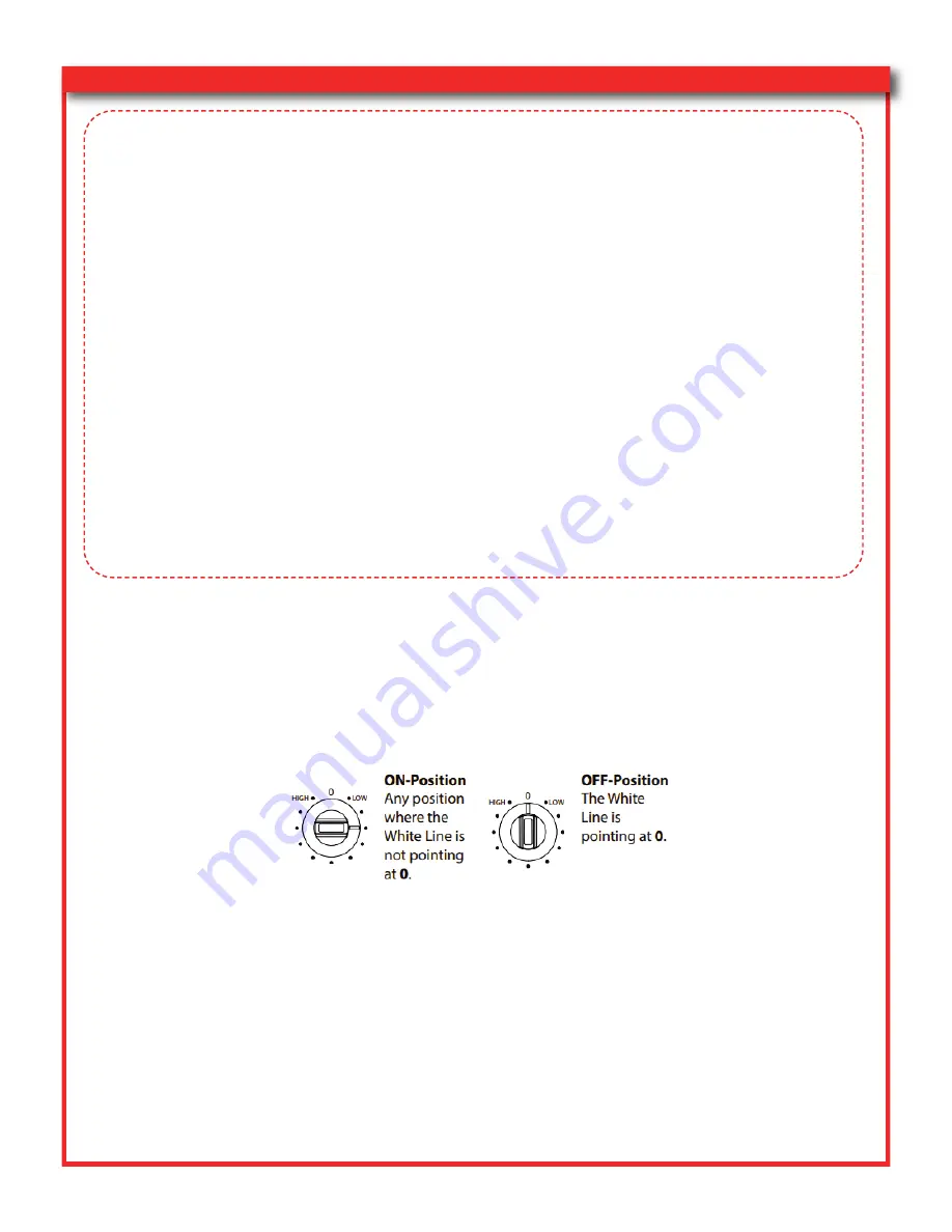
Turn the control knob to the desired temperature to power on the griddle appliance; unit is

3

now ready for operation.  Temperature can be adjusted from 68-450°F (20-230°C)

As you turn the control knob the digital display will show the temperature.  Stop turning the

4

knob when the desired temperature is displayed.

POWER OFF PROCEDURE

1. Turn the Control knobs on the appliance to the OFF-Position.

NOTE: The filtration system will continue to operate for a period of 

30 Minutes

before

turning off . DO NOT press the power button on the column to initiate an abrupt shutdown

of the unit. Repeated abrupt shutdowns may damage the appliances and void warranty.

The digital displays will show “HOT” while the griddle surface is cooling. Once the surface is cool

the induction units will go into the stand-by mode. When in the stand-by mode, the point on the

display blinks once every second.

IMPORTANT!

Ensure the control knob is in the off position when the unit is not in use.

Summary of Contents for Valere Series

Page 1: ...ction Station MC 59 FPS G2 R3 2 0 This Manual Includes Installation Safety and Routine Maintenance Instructions for this appliance THIS MANUAL MUST BE READ AND UNDERSTOOD BY ALL PERSONS USING OR IN ST...

Page 2: ...NSTRUCTIONS AND WARNINGS 2 3 RECEIVING AND INSPECTION 4 INSTALLATION 4 FIRE SUPPRESSION 4 ELECTRICAL SPECIFICATIONS 5 FEATURES AND OPERATING INSTRUCTIONS 5 7 FILTER INSTALLATION AND REPLACEMENT SCHEDU...

Page 3: ...e not covered by this warranty Conversion to correct voltage and or phase is the customer s responsibility All problems due to electrical connections not made in accordance with electrical code requir...

Page 4: ...ng surface Persons with a cardiac pacemaker should consult their doctor whether they are safe near an induction unit Do not obstruct the air intake and exhaust of the induction appliances to avoid uni...

Page 5: ...work that could get lodged in the blower intake or wheel Do not store or use gasoline or other flammable vapors or liquids in the vicinity of this or any other appliance Do not move the mobile cooking...

Page 6: ...0000259 Cutting Board 1 INSTALLATION Installation Use and Maintenance of this product are to be in accordance with the Standard for Ventilation Control and Fire Protection of Commercial Cooking Operat...

Page 7: ...a NEMA 6 50P plug before connecting 4 always make sure the voltage and frequency are correct and match the nameplate Circuit breakers contain international labels for On and Off as shown below 5 MODEL...

Page 8: ...y and will recover any temperature loss quickly from cold food POWER ON PROCEDURE Press the power button on the left column to turn on the filtration system 1 Check the screen to make sure no error co...

Page 9: ...heating surface of the induction appliance Metallic objects heat up very quickly when placed on the induction cooker Avoid placing any objects sensitive to magnetism on the glass cooking surface Do no...

Page 10: ...FLE FILTERS Baffle Filters are re usable dishwasher safe and should be cleaned daily Remove the Baffle Fil ters by pulling up on the filter and sliding the bottom out as shown below Only use genuine K...

Page 11: ...ooner 1 Remove the Baffle Filters as shown on Page 8 Figure 1 2 Remove the Filter Access Panel as shown below by removing the panel knobs 3 Slide the bottom of the access panel towards you and then li...

Page 12: ...affle Filters as shown on Page 8 Figure 1 2 Remove the Filter Access Panel 3 Remove the Pre Filter 4 Remove the HEPA filter by lifting it up and sliding it out of the duct work 5 Replace the HEPA Filt...

Page 13: ...nths or sooner 1 Remove the back panel by lifting up on it 2 Open the rear access panel shown below 3 Remove the carbon Odor Filter 4 Replace the Carbon Odor Filter in the correct orientation air flow...

Page 14: ...is shutdown Allow the appliances to cool before pro ceeding 2 Clean the cooking appliances by following the manufacturer s supplied cleaning instructions shown below Garland s full user manual for gr...

Page 15: ...its Ceran Glass Cleaning of the Ceran glass is identical to other similar surfaces like glass Do not use corro 1 sive or abrasive cleaning agents such as grill and oven sprays stain and rust removers...

Page 16: ...the front doors and remove the appliance AIR INTAKE FILTERS shown below by pressing up on its corners 2 Clean the AIR INTAKE FILTERS Part No 40000004 in a dishwasher Wipe the Filters DRY before inser...

Page 17: ...inside the duct work Do not grab onto the fusible links or the cable supporting them 5 Reinstall the HEPA PRE FILTER FRONT FILTER ACCESS PANEL and BAFFLE FILTERS in this order 6 Remove the back panel...

Page 18: ...BE HOT Use Caution When Removing 10 Griddle Control Panel Use to turn on off griddle and set cooking temperature 11 HOB Control Knob Use to turn on off Hob and set temperature 12 Status Display Scree...

Page 19: ...r Plug NEMA 6 50P power plug Disconnect before per forming service 4 Blower Assembly Do not place any foreign objects in the duct work that may obstruct the blower 5 Motor 1 HP TEFC 56C Frame 3Phase M...

Page 20: ...tall missing filters Check air pressure ports inside the hood for obstruction If necessary disconnect the air line via push to fitting to clear blockage Reinstall the air line making sure it s fully s...

Page 21: ...uit breakers are not tripped Ventilation does not turn on Confirm fire suppression is charged and in ready state Confirm all closure panels are closed Check blower for any obstruction inside the duct...

Page 22: ...essfully prevent appliance movement 7 Replace if necessary Verify that the extinguishing system is in its proper location 8 Verify that the manual actuators are unobstructed 9 Verify that the tamper i...

Page 23: ...ne 9 by cutting or melting the last link Make certain that the Systems Releasing Module fires the gas valve closes and all auxiliary devices connected to the micro switch operate or stop Replace all f...

Page 24: ...ink line repair the terminal link and re set the control head 6 Once the Systems Releasing Module is reset the mechanical pull station must be checked To 7 do so pull the handle on the remote pull sta...

Page 25: ...required REQUIRED MAINTENANCE Description Frequency Performed By Fire Suppression System Inspection per manufacturer s recommendations Monthly Owner User Change Filters As Needed Owner User Clean Mob...

Page 26: ...24 MAINTENANCE LOG K D s E E E E E E E E E E E E s d d d E d d d d K...

Reviews: