Installation
ProLine 2200 User’s Manual REV N
This information is subject to the controls of the Export Administration Regulations [EAR]. This information shall not be provided to
non-U.S. persons or transferred by any means to any location outside the United States contrary to the requirements of the EAR.
3-6
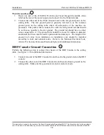
Work Ground Lead
1. Route one end of the #1/0AWG Work Ground Lead through the middle strain
relief on the rear of the power supply and connect it to the Work terminal.
2. Connect the other end of the Work Ground Lead to the star ground point on the
cutting table. The star ground point is generally referred to as the common
ground point on the cutting table where all subsystems of the machine are
grounded. This point is then connected to a driven earth ground rod that should
be as close as possible to the star ground. The ground rod should have no other
wires connected to it. The ground rod should be at least 3/4 inches in diameter
and should be driven into the earth’s permanent moisture layer. The length of the
ground rod varies from installation to installation and should be installed
according to local and national codes. Refer to the National Electrical Code,
Article 250, Section H, Ground Electrode System for additional information.
RHF Console Ground Connection
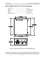
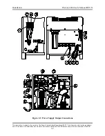
Perform the following steps to connect the chassis of the RHF Console to the cutting
table. See Figure 3-3 for additional information.
1. Connect one end of the RHF Console Ground Lead to the ground stud on the RHF
console.
2. Connect the other end of the RHF Console Ground Lead to chassis ground on the
cutting table. Make sure that good metal-to-metal contact is made.
7
8

