Installation
ProLine 2200 User’s Manual REV N
This information is subject to the controls of the Export Administration Regulations [EAR]. This information shall not be provided to
non-U.S. persons or transferred by any means to any location outside the United States contrary to the requirements of the EAR.
3-8
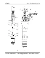
Torch Leads to RHF Console Connections
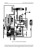
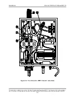
Perform the following steps to connect the torch leads to the RHF console. See Figure 3-
4 for additional information.
Note: When making hose connections, only tighten the brass
fittings enough to make water or gas seals. The fittings are
subject to damage if over tightened.
Braided Shield
•
Remove the threaded ring from the brass shield connector on the end of the
braided shield. Route the torch leads through the opening in the RHF console and
push the shield connector through the hole until it is seated against the side of the
console.
•
Slide the threaded ring over the torch leads, thread it onto the brass shield
connector, and
tighten firmly
. The shield connector should ground the braided
shield to the case of the RHF console in order to help reduce high frequency noise
emission. Using an ohmmeter, measure for zero ohms between the braided shield
and the ground stud located on the outside of the RHF console.
Torch Electrode/Coolant Supply Lead
•
Connect the Torch Electrode/Coolant Supply Lead to the brass cathode manifold.
Note that the Torch Electrode/Coolant Supply Lead has right hand threads.
Torch Coolant Return Lead
•
Connect the Torch Coolant Return Lead to the brass cathode manifold. Note that
the Torch Coolant Return Lead has left hand threads.
Torch Nozzle Lead
•
Connect Torch Nozzle Lead to the angled bracket on the red standoff. Note that
the Torch Nozzle Lead has right hand threads.
Torch CTP Sensor Lead
•
Connect the #18AWG Torch CTP Sensor Lead to the red standoff as shown.
9
10
11
12
13

