Installation
ProLine 2200 User’s Manual REV N
This information is subject to the controls of the Export Administration Regulations [EAR]. This information shall not be provided to
non-U.S. persons or transferred by any means to any location outside the United States contrary to the requirements of the EAR.
3-16
CNC Machine Interface Connections
Perform the following steps to properly interface the ProLine 2200 system with a CNC
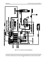
cutting machine. See the system schematic for additional information.
Plasma Start Signal
•
The ProLine 2200 requires a contact closure between P8 pins 3 and 4 to commence
the cutting sequence. The cutting sequence is terminated when the contacts are
opened. The contacts should be rated for 12VDC - 10mA. If the ProLine 2200 is
ordered with the integrated Inova system, see below for interface information.
Arc Hold / IHS Complete Signal
•
The ProLine 2200 requires a contact closure between P8 pins 10 and 11 to inhibit
arc starting even though a plasma start signal has been applied to the unit. When
the arc hold / IHS complete contacts are opened, the cutting arc is initiated. This
feature is used to decrease cycle time by allowing pre-cut gas and contact
sequencing to occur simultaneously with initial torch height positioning. The
contacts should be rated for 12VDC - 10mA. If the ProLine 2200 is ordered with
the integrated Inova system, see below for interface information.
Motion Output Signal
•
The ProLine 2200 provides a maintained contact closure output between P8 pins 12
and 14 as long as a cutting arc is maintained between the torch and the workpiece.
The motion contacts are rated for .6A - 125VAC / .6A - 110VDC / 2A - 30VDC. If
the ProLine 2200 is ordered with the integrated Inova system, see below for
interface information.
Inova Connections (optional)
•
When the ProLine 2200 is ordered with the integrated Inova torch height control
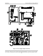
system, connect the Inova C cable between P8 on the rear of the power supply and
P3 on the Inova control panel. The C cable is used to interface the plasma start,
plasma hold, and machine motion signals between the Inova and the ProLine 2200.
Next, connect the Inova D cable between P7 on the rear of the power supply and P2
on the Inova control panel. The Inova D cable is used to interface the cutting arc
voltage and plate sensing circuit between the Inova and the ProLine 2200. Next,
connect the Inova E cable between the Work terminal on the ProLine power supply
and the Ground lug on the Inova control panel. Note that the E cable is not a safety
ground. It is part of the voltage feedback circuit used for arc voltage control. See
the Inova manual for details on x/y machine, operator’s remote, and positioner
interface.

