Operation
ProLine 2200 User’s Manual REV N
This information is subject to the controls of the Export Administration Regulations [EAR]. This information shall not be provided to
non-U.S. persons or transferred by any means to any location outside the United States contrary to the requirements of the EAR.
4-4
Setting up a Cut
Note: When installing the torch parts, do not use an excessive amount of o-ring lubricant.
Also, ensure that the lubricant is placed only on the o-rings. Excess lubricant can interfere
with gas flow, cause starting problems, and shorten consumable life.
1. Turn off the primary power to the unit.
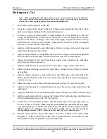
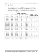
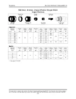
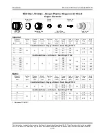
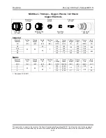
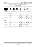
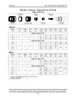
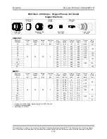
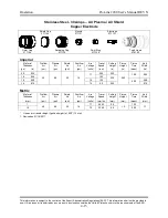
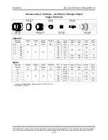
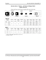
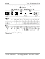
2. Using the cutting charts found in the rear of this section, determine the proper torch
parts and cutting conditions for the material being cut.
3. If using a copper electrode, apply a small amount of o-ring lubricant to the two
o-rings on the electrode. Then, use the tool (P/N 277087) to tighten the electrode
into the torch head. If using a silver electrode, apply a small amount of o-ring
lubricant to the o-ring on the electrode. Then, use the tool (P/N 279061) to tighten
the silver electrode into the torch head.
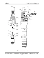
4. Apply a small amount of o-ring lubricant to the two o-rings on the swirl ring and
insert the swirl ring into the nozzle.
5. Apply a small amount of o-ring lubricant to the two o-rings on the nozzle and push
the swirl ring/nozzle assembly into the torch head until it is seated properly.
6. Inspect the threads on the torch base/head, copper inner retaining cap, and brass
outer cap and clean as necessary.
7. Install a small amount of o-ring lubricant to the three o-rings on the torch head.
8. Install the inner retaining cap onto the torch head. Tighten the cap firmly but do not
over tighten.
9. Apply a small amount of o-ring lubricant to the shield cap o-ring and install the
shield cap into the brass outer cap.
Note: Make sure the shield cap o-ring is seated properly
inside the outer cap.
10. Install the outer cap onto the torch head and tighten firmly. Do not over tighten.
11.
Apply a small amount of o-ring lubricant on each of the seven o-rings on the top of the
torch head.
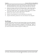
12. Align the indicator on the torch head (small circle) with the one on the torch base (slot).
13. Apply enough upward force to engage the threads while tightening the attachment ring.
Turn the attachment ring to the LEFT to tighten.
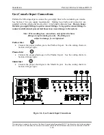
14. Connect the correct preflow, plasma, and shield gas types to the gas inlet ports on
the rear of the gas console.
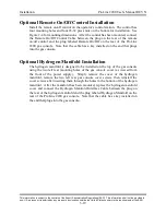
When using H17 as the plasma gas, connect the H17 gas supply
to the Hydrogen In port on the H17 manifold and move the Plasma Out hose from the ProLine
2200 gas console to the Hydrogen Out port on the H17 manifold. Do not route H17 through the
ProLine 2200 gas console. NOTE: Always turn the system off prior to changing gases.
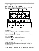
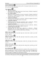
15. Depress and hold the Power On button until the Coolant Flow status LED
illuminates. If the Coolant Flow LED fails to illuminate after 10 seconds, see the
maintenance section for possible causes and solutions.

