ProLine 2200 User’s Manual REV N
This information is subject to the controls of the Export Administration Regulations [EAR]. This information shall not be provided to
non-U.S. persons or transferred by any means to any location outside the United States contrary to the requirements of the EAR.
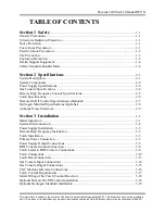
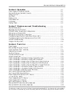
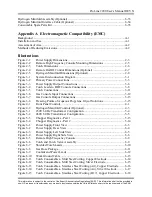
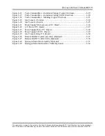
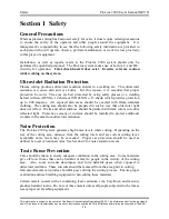
TABLE OF CONTENTS
Section 1 Safety
..……………………………………..…………………………….
1-1
General Precautions .…………………………………………………..……….…..……… 1-1
Ultraviolet Radiation Protection ..…………………………………………………………. 1-1
Noise Protection .……………………………………………………..……………………. 1-1
Toxic Fume Prevention ...…………………………………………………………..……… 1-1
Electric Shock Prevention ...……………………………………………………….….…… 1-2
Fire Prevention ...…………………….………………………………….…………………. 1-3
Explosion Prevention .....…….….………….…………………………………..………….. 1-3
Health Support Equipment ...…………………….……………………………….………... 1-4
Safety Standards Booklet Index ...…………………….……………………………….…... 1-4
Section 2 Specifications
...….……...
……………………………………………… 2-1
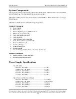
System Description ...……………………………………………………………………… 2-1
System Components ………………………………………………………………………. 2-2
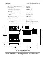
Power Supply Specifications ……………………………………………………………… 2-2
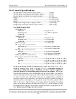
Gas Console Specifications ...................……………………………………………………2-4
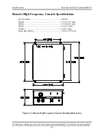
Remote High Frequency Console Specifications …………………………………………. 2-5
Torch Specifications ...…………………………………………………………………….. 2-6
Remote On/Off Control Specifications (Optional) ..………………………………………. 2-7
Hydrogen Manifold Specifications (Optional) ........………………………………………. 2-8
Airborne Noise Emissions ......…………………………………………………………….. 2-9
Section 3 Installation
.....………………………………………………………… 3-1
Initial Inspection .......……………………………………………………………………… 3-1
System Interconnection .…………………………………………………………………… 3-2
Power Supply Installation .………………………………………………………………… 3-3
Remote High Frequency Installation ……………………………………………………… 3-3
Torch Installation ......……………………………………………………………………… 3-3
Primary Power Connection ...……………………………………………………………… 3-3
Power Supply Output Connections .......…………………………………………………… 3-5
RHF Console Ground Connection ....……………………………………………………… 3-6
Torch Leads to RHF Console Connections ..……………………………………………… 3-8
Torch Connections ....……………………………………………………………………… 3-10
Torch Head Connection…………………………………………………………………… 3-13
Gas Console Input Connections ....................……………………………………………… 3-14
Gas Console Output Connections .........................………………………………………… 3-15
CNC Machine Interface Connections ...…………………………………………………… 3-16
Torch Coolant Requirements ....…………………………………………………………… 3-17
Initial Filling of the Torch Coolant Reservoir…………………………………………… 3-18
Optional Remote On/Off Control Installation ......………………………………………… 3-19
Optional Hydrogen Manifold Installation .............………………………………………… 3-19


