


Operation
ProLine 2200 User’s Manual REV N
This information is subject to the controls of the Export Administration Regulations [EAR]. This information shall not be provided to
non-U.S. persons or transferred by any means to any location outside the United States contrary to the requirements of the EAR.
4-14
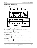
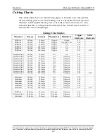
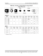
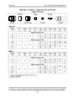
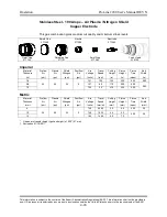
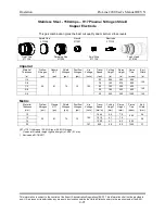
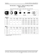
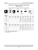
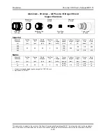
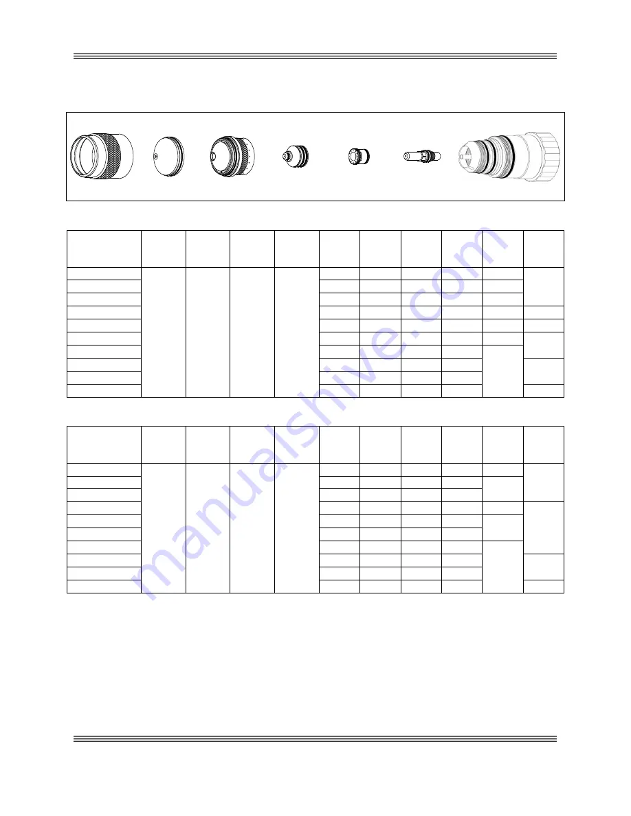
Mild Steel - 200 Amps – Oxygen Plasma / Air Shield
Copper Electrode
Shield Cap
Nozzle
Electrode
277274
277289
277291
Outer Cap
Retaining Cap
Swirl Ring
Torch Head
277154
277266
277143
279150
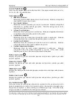
Imperial
Material
Thickness
Preflow
Air
Plasma
Oxygen
Shield
Air
Postflow
Air
Arc
Voltage
Travel
Speed
Cutting
Height
Pierce
Height
Pierce
Time
Kerf
Width
(in)
(psi)
(psi)
(psi)
(psi)
(volts)
(ipm)
(in)
(in)
(msec)
(in)
1/4
20
82
58
0
125
230
.040
.200
300
.150
3/8
130
140
.090
.250
400
1/2
133
120
.115
.300
500
5/8
137
100
.130
.350
600
.152
3/4
140
75
.150
.400
800
.153
1
147
50
.175
.450
1000
.155
1.25
155
25
.240
.500
1500
1.5 **
165
17
.300
.350
158
1.75 **
175
12
.350
.350
2.0 **
185
7
.500
.500
.160
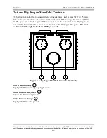
Metric
Material
Thickness
Preflow
Air
Plasma
Oxygen
Shield
Air
Postflow
Air
Arc
Voltage
Travel
Speed
Cutting
Height
Pierce
Height
Pierce
Time
Kerf
Width
(mm)
(psi)
(psi)
(psi)
(psi)
(volts)
(mm/m)
(mm)
(mm)
(msec)
(mm)
6
20
82
58
0
124
6100
.8
4.9
300
3.8
10
130
3480
2.3
6.5
500
12
132
3160
2.7
7.3
16
137
2515
3.3
8.9
800
3.9
20
141
1810
3.8
10.3
1000
25
146
1310
4.3
11.3
32
155
610
6.1
12.7
1500
38 **
164
435
7.5
8.9
4.0
45 **
175
295
9.2
9.2
50 **
183
195
12.2
12.2
4.1
* Use an arc transfer height (ignition height) of .200” (4.9 mm)
** Edge start recommended
1. Revised on 01/18/2011


