ProLine 2200 User’s Manual REV N
This information is subject to the controls of the Export Administration Regulations [EAR]. This information shall not be provided to
non-U.S. persons or transferred by any means to any location outside the United States contrary to the requirements of the EAR.
Hydrogen Manifold Assembly (Optional) ............................................................................ 6-33
Hydrogen Manifold Interface Cable (Optional) ................................................................... 6-34
Consumable Spare Parts Kit ................................................................................................. 6-35
Appendix A Electromagnetic Compatibility (EMC)
Background ........................................................................................................................... A-1
Installation and Use ...............................................................................................................A-1
Assessment of Area ...............................................................................................................A-2
Methods of Reducing Emissions .......................................................................................... A-2
Illustrations
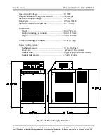
Figure 2-1
Power Supply Dimensions ............................................................................ 2-3
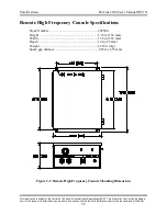
Figure 2-2
Remote High Frequency Console Mounting Dimensions ............................ 2-5
Figure 2-3
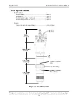
Torch Dimensions ......................................................................................... 2-6
Figure 2-4
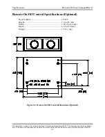
Remote On/Off Control Dimensions (Optional) ........................................... 2-7
Figure 2-5
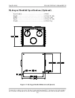
Hydrogen Manifold Dimensions (Optional) ................................................. 2-8
Figure 3-1
System Interconnection Diagram .................................................................. 3-1
Figure 3-2
Primary Power Connections ......................................................................... 3-3
Figure 3-3
Power Supply Output Connections ............................................................... 3-6
Figure 3-4
Torch Leads to RHF Console Connections .................................................. 3-8
Figure 3-5
Torch Connections ........................................................................................ 3-11
Figure 3-6
Gas Console Input Connections .................................................................... 3-12
Figure 3-7
Gas Console Output Connections ................................................................. 3-13
Figure 3-8
Freezing Points of Aqueous Propylene Glycol Solutions ............................. 3-15
Figure 4-1
Front Panel Controls ..................................................................................... 4-1
Figure 4-2
Hydrogen Manifold Controls (Optional) ...................................................... 4-3
Figure 5-1
230V 60 Hz Transformer Configuration .......................................................5-4
Figure 5-2
460V 60 Hz Transformer Configuration .......................................................5-5
Figure 5-3
Chopper Diagnostics - Part 1 ........................................................................ 5-13
Figure 5-4
Chopper Diagnostics - Part 2 ........................................................................ 5-14
Figure 6-1
Power Supply Front View ............................................................................. 6-3
Figure 6-2
Power Supply Rear View .............................................................................. 6-4
Figure 6-3
Power Supply Left Side View .......................................................................6-5
Figure 6-4
Power Supply Right Side View .................................................................... 6-6
Figure 6-5
Remote High Frequency Console ................................................................. 6-8
Figure 6-6
Torch and Torch Valve Assembly ................................................................ 6-9
Figure 6-7
Shielded Torch Leads ................................................................................... 6-10
Figure 6-8
Gas Hose Package ......................................................................................... 6-11
Figure 6-9
Coolant and Power Leads ............................................................................. 6-12
Figure 6-10 Work Ground Cable ...................................................................................... 6-13
Figure 6-11 Torch Consumables - Mild Steel Cutting, Copper Electrode....................... 6-14
Figure 6-12 Torch Consumables - Mild Steel Cutting, Silver Electrode......................... 6-15
Figure 6-13 Torch Consumables - Stainless Steel Cutting (Air), Copper Electrode........ 6-16
Figure 6-14 Torch Consumables - Stainless Steel Cutting (Air), Silver Electrode.......... 6-17
Figure 6-15 Torch Consumables - Stainless Steel Cutting (H17), Copper Electrode...... 6-18


