Maintenance and Troubleshooting
ProLine 2200 User’s Manual REV N
This information is subject to the controls of the Export Administration Regulations [EAR]. This information shall not be provided to
non-U.S. persons or transferred by any means to any location outside the United States contrary to the requirements of the EAR.
5-7
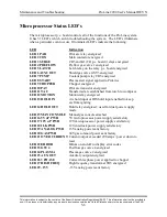
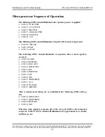
Microprocessor Sequence of Operation
The following LED’s should illuminate after primary power is applied:
•
LED 16 5V uP PWR
•
LED 17 12V uP PWR
•
LED 18 ILK PWR
•
LED 19 ANALOG PWR
•
LED 20 GAS PWR
•
LED 29 –15V
The following LED’s should illuminate when the ON button is depressed:
•
LED 26 3 PHASE
•
LED 7 PUMP
•
LED 5 LATCH
The following LED’s should illuminate in sequence after a start signal is
received:
•
LED 8 START
•
LED 4 PREFLOW
•
LED 6 AUX2 OUT
•
LED 14 HOLD OUT
•
LED 2 CON
•
LED 9 CHOPPER
•
LED 1 PAR
•
LED 10 PAT
•
LED 27 HIGH FREQ
•
LED 11 TAC
•
LED 24 PLASMA
•
LED 12 MOTION
After a transferred cutting arc is established, the following LED’s will go
out:
•
LED 14 HOLD OUT
•
LED 27 HIGH FREQ
•
LED 4 PREFLOW
•
LED 10 PAT
When the start signal is removed, all of the cut cycle LED’s will extinguish
except for LED 23 GSV4, which will illuminate for approximately 3 seconds
and then go out
.

