- 10 -
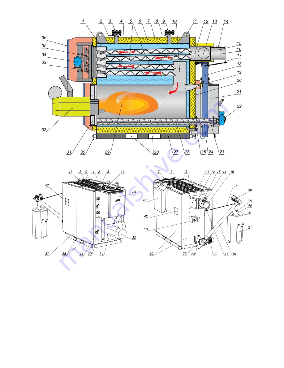
Fig. 1. Boiler construction
Fig. 2. External elements of the boiler.
1. Boiler body. 2. Emergency thermostat temperature sensor mounting location. 3. Outflowing water branch pipe.
4. Installation location of water temperature measuring devices. 5. Pipe heat exchanger with rotary turbulizers. 6. Thermal
insulation cover. 7. Corrugated top cover. 8. Installation location of water temperature measuring devices. 9. Incoming water
branch pipe. 10. Draught measurement branch pipe. 11. Lugs for boiler lifting. 12. Smoke collector. 13. Soot cleaning lids.
14. Lambda probe mounting location*. 15. Installation location of smoke temperature measuring device. 16. Flue pipe. 17. Ash
removal conveyor fastening loop. 18. Ash removal conveyor. 19. Hearth peephole. 20. Decorative panels. 21. Ash container.
22. Actuator for ash from boiler extraction auger. 23. Protective screw connecting the ash removal auger with its actuator.
24. Tray for ash from the boiler. 25. Water outlet branch pipe. 26. Ash removal auger from boiler. 27. Boiler pad. 28. Lifting
holes in boiler pad. 29. Hearth. 30. Lugs for boiler pulling. 31. Hearth door. 32. Burner. 33. Heat exchanger door. 34. Heat
exchanger cleaning mechanism drive. 35. Heat exchanger cleaning mechanism. 36. Heat exchanger cleaning mechanism
service panel. 37. Ash removal conveyor fastening chain. 38. Ash removal conveyor drive. 39. Fastening of container
connection duct cover. 40. Container connection duct cover. 41. Container cover. 42. Branch pipe connections for measurement
of draught in the chimney (see Fig. 6). 43. Control cabinet (can be installed at another location or on the boiler house wall).
44. Door closure sensors.
* Installed (presented) only by prior agreement in the contract.
Summary of Contents for Kalvis-100MG
Page 2: ......


