
Controlling units via DMX
- each unit uses 8 DMX channels
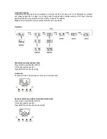
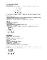
To set the DMX address
1.
Press the function button until *** is displayed (range 001-512)
2.
Using the up / down buttons select the desired DMX staring address
3.
Press the enter button to confirm
4.
Continue this formula to address any additional units
Note on setting the DMX address of units - if one or several units are to be controlled at the same time with the same
features set, all units DMX address needs to be the same
Example all units to 001
If individual control of several units is required
Each unit must have its on unique address and no channels must cross
Example unit 1 set to 001 – unit 2 to 09 etc adding 8 clear channels each time
Master slaving units with no DMX controller
Set the master unit to the desired setting
Example auto or sound
Set all other units to slave mode
To set slave mode press the function button until SLA is displayed then press the enter button to confirm
Only one unit must be set as a master and all other units as a slave
Connect each unit together via a 3pin DMX lead
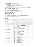
DMX Protocol
CHANNEL
VALUE
FUNCTION
CH1 MODE
000-063
Laser black out
064-127
Auto show
128-191
Sound activated show (music)
192-255
DMX MODE (other channels activated)
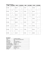
CH2 PATTERN
000-255
32 Patterns as shown in PATTERN LIST
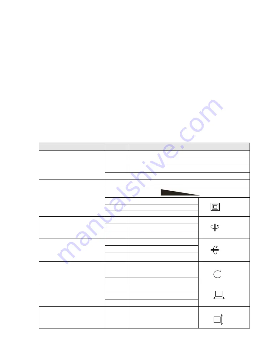
CH3 ZOOMING
000-127
100%-5% Size
128-169
Zooming in
170-209
Zooming out
210-255
Zooming in and out
CH4 Y AXIS ROLLING
000-127
0 -359 degree fixed Y axis rolled
128-191
Clockwise rolling
192-255
Anticlockwise rolling
CH5 X AXIS ROLLING
000-127
0 -359 degree fixed X axis rolled
128-191
Clockwise rolling
192-255
Anticlockwise rolling
CH6 Z AXIS ROLLING
000-127
0 -359 degree fixed Z axis rotate
128-191
Clockwise rotating
128-255
Anticlockwise rotating
CH7 X AXIS MOVING
000-127
128 different fixed position on X
128-191
Clockwise moving
128-255
Anticlockwise moving
CH8 Y AXIS MOVING
000-127
128 different fixed position on Y
128-191
Clockwise moving
128-255
Anticlockwise moving


