AC power
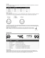
The unit is supplied with a power plug appropriate to its voltage. Should any other connections be required they must be carried
out with the following configuration:
Cable (EU)
Cable (US)
Pin
International
Brown
Black
Live
L
Light blue
White
Neutral
N
Yellow/green
Green
Earth
DMX-512 connection
If you are using a standard DMX controller, you can connect the DMX output of the controller directly to the DMX input of the first
unit in a DMX chain. If you wish to connect a DMX controller with other XLR outputs you will need to use adapter cables.
1 = Shield
DMX output
2 = Signal (-)
DMX input
3 = Signal (+)
Connect the DMX output of the first unit in a DMX chain with the DMX input of the next unit in the chain. Always connect the the
output of one unit with the input of the next unit until all units are connected. If you use a controller with 5 pin DMX connection you
will need to use a 5 pin to 3 pin adapter.
Caution
at the unit, the DMX cable has to be terminated with a terminator. Solder a 120 Ohm resistor between
Signal (-) and Signal (+) into a 3-pin XLR connector and plug this into the DMX output of the last unit in the chain.
Rear panel features
q
w
r
e
y
t
Number Feature
Function
1
Power supply input
Attach the mains cable here.
2
Microphone
Mic for Sound-to-Light operation.
3
Function setting LED
Displays the current operating mode.
4
Function buttons
Menu buttons to control the operating mode of the laser.
5
DMX input
3 pin XLR connector for DMX512 input communication.
6
DMX output
3 pin XLR connector for DMX512 output communication.
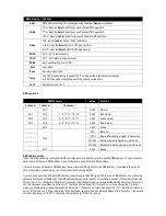
Function setting
Using the four function buttons on the rear of the unit you can set the operating mode of the unit. Press the
Menu
button to
display the different functions (see table below for a description of the functions). Use the
Up
or
Down
arrow buttons to make
your selection. When you have chosen your desired mode, press the
Enter
button to confirm the change.


