LRWMANUAL 0321
KAM CONTROLS, INC.
10
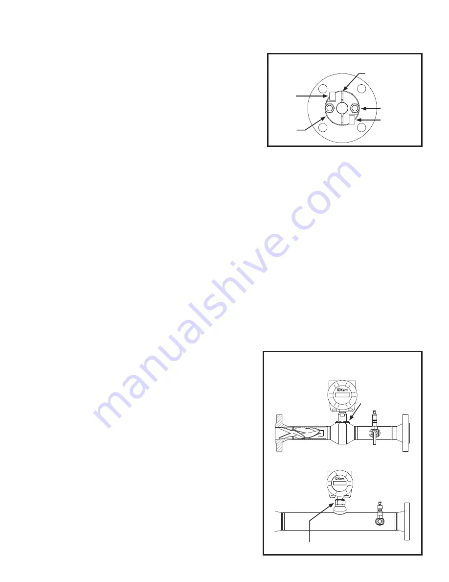
REMOVING THE LRW
®
SENSOR FROM
FLOW THROUGH SPOOL
1.
To remove the LRW
®
sensor, first shut off power to the
instrument.
2.
Discontinue flow in loop from the main line and drain fluid
from loop.
3.
Using a 5/32" Allen wrench, remove the (10) 32 x 5/8"
Hex screws with on collar (2" models) or unscrewed from
spool body (3" and 4" models) using the 1 3/4" wrench flat.
FIG. 3-10.
4.
The probe can then be lifted from the cell for testing/
inspection/calibration purposes.
Removal should be conducted in accordance with all regional
and class requirements.
FIG. 3-10
I N S TA L L AT I O N C O N T I N U E D
REMOVING AN INSERTABLE LRW SENSOR
1.
To remove the LRW sensor, first shut off power to the instrument.
2.
Loosen the Socket Cap Screws on the Lock Down Collar, using a 3/8" Allen wrench.
3.
Loosen Hex Nuts 1/2 turn.
4.
Slide the LRW sensor upward until the probe rests inside the seal housing. There is a mechanical stop when the
unit is fully retracted.
5.
Retighten the Socket Cap Screws.
6.
Next, close the Full-opening Ball Valve tightly. Drain oil from valve if possible.
7.
The LRW sensor may now be unbolted from the system.
NOTE: If line pressure exceeds 100 psi, use a KAM
®
IT Insertion Tool when installing/removing the KAM
®
LRW sensor.
Removal should be conducted in accordance with all regional and class requirements.
Water 0.377 %
Temp 28.278 C
www.KAM.com
+1 713 784 0000
sales@kam.com
Made in the USA
LRW Low Range Watercut
Water 0.377 %
Temp 28.278 C
www.KAM.com
+1 713 784 0000
sales@kam.com
Made in the USA
LRW Low Range Watercut
Hex screws
2" LRW Flow Through model
3" and 4" LRW Flow Through models
1 3/4" wrench flat
12.
Re-tighten the Socket Cap Screws so that the gaps between
the two halves of the locking collar are the same distance.
FIG. 3-9.
13.
Tighten the hex nuts holding down the Locking Collar one
half turn (FIG. 3-9). These should never be over-tightened.
Their major function is to apply light pressure on the chevron
packing to ensure a seal between the seal housing body and
the insertion shaft.
SECTION A-A
SCALE 1 / 2
1
1
2
2
A
A
B
B
MATERIAL
FINISH
DRN
THIS DRAWING IN DESIGN AND
DETAIL IS THE PROPERTY OF
KAM CONTROLS INCORPORATED.
IT SHALL NOT BE REPRODICED
AND SHALL BE RETURNED TO US
ON DEMAND
ALL RIGHTS RESERVED
APPVD
SCALE
DATE
DWG NO.
REV
TITLE
UNLESS OTHERWISE
SPECIFIED
ALL DIM IN INCHES
ANGULAR TOL ±1/2
FRACTIONAL TOL ±1/64
3 PLACE DEC ±0.005
2 PLACE DEC ±0.010
REMOVE ALL BURRS
BREAK SHARP EDGES
DO NOT SCALE DWG
SHEET
SS316
Gerry Alejos
1:2
03-13-2013
A
2"-150 Seal Housing
Assembly
211-001-000
Kam
Controls
Incorporated
3939 Ann Arbor Dr.
Houston TX 77063
USA
WWW.KAM.COM
1
OF
1
A
1/4
5/32
FIG. 3-9
TOP VIEW LOCKING COLLAR
Socket Cap
Screw
Locking
Collar
Gap
Socket Cap
Screw
Hex Nut


