LRWMANUAL 0321
KAM CONTROLS, INC.
8
I N S TA L L AT I O N C O N T I N U E D
5.
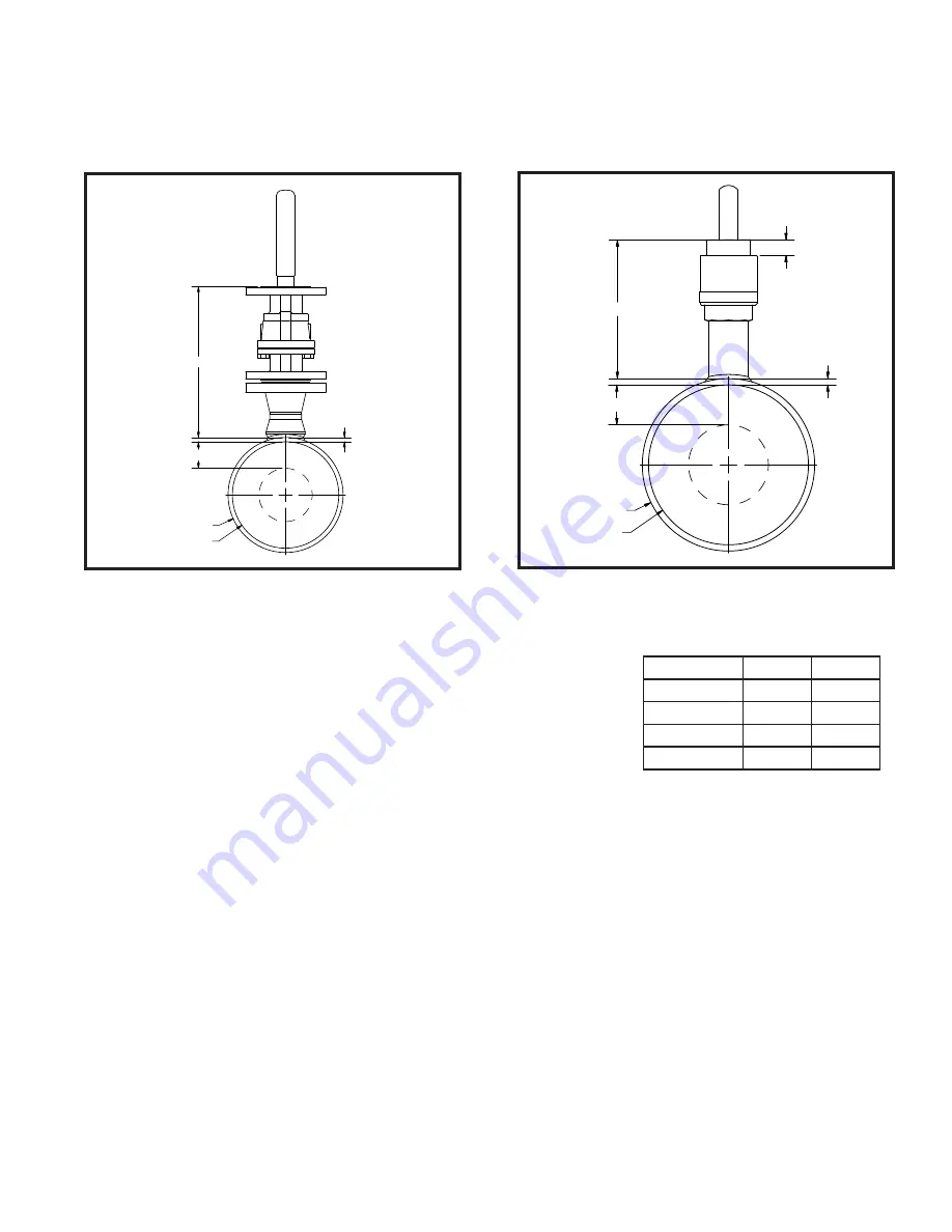
Measure the distance (D1) from the outside diameter of main pipe to the end of the connection where the LRW
®
sensor is going to be installed. FIG. 3-6a and FIG. 3-6b.
D1
WT
Ls
Pipe OD
Pipe ID
Lt
D1
WT
Pipe OD
Pipe ID
Ls
FIG. 3-6a
FIG. 3-6b
6.
Calculate the insertion distance:
For flanged Seal Housing models
MID
–
Minimum Insertion Distance
D1
–
Distance from the top of the valve to the pipe
Lg
–
Gasket Width (Typical 0.134")
WT
–
Pipe Wall Thickness
Ls
–
Pipe ID x 0.25 (Measurement Area Length)
Ds
–
Pipe ID x 0.5 (Measurement Diameter Area)
Minimum Insertion Distance (MID)=D1 + Lg + WT + Ls + LRW Factor
Example: D1=14"
Lg=0.134"
WT=0.25"
ID=8.125"
LRW Factor 2" 150#=1"
MID=14 + 0.134 + 0.25 + (8.125 x 0.25) + 1
MID=17.41"
Take note of the calculated MID and proceed to step 7.
Class Rating
2" Size
3" Size
150#
1.00"
1.20"
300#
1.12"
1.37"
600#
1.50"
1.75"
900#
2.00"
2.00"
TABLE 3-1 LRW FACTOR - Flanged SH


