


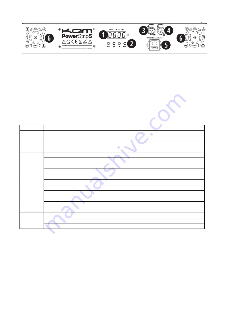
Key to rear panel diagram
1.
LED function setting display - shows the various menus and the selected functions.
2.
Menu buttons - used to select the different menu items.
3.
DMX input - 3 pin male XLR interface for DMX connections.
4.
DMX output - 3 pin female XLR interface for DMX connections.
5.
Mains power input IEC socket and integrated fuse holder. Connect the supplied IEC cable to the input and the mains.
6.
Fan vents - do not cover.
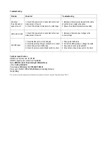
Main menu
To select any of the menu options, press the MENU button to select the mode required.
Once you have made a selection then press ENTER to confirm. Use the UP and DOWN buttons to choose the desired menu option.
Mode selection
Press the MENU button, the following functions can be selected and then confirmed using the ENTER button:
LED display Function description
A001
8 channel address
001-512
Up or down buttons can increase or decrease the address
H001
20 channel address
001-512
Up or down buttons can increase or decrease the address
h001
15 channel address
001-512
Up or down buttons can increase or decrease the address
CC00
7 colour hopping
01-99
Up or down buttons can change the speed of hopping
CP00
7 colour gradual change
01-99
Up or down buttons can increase or decrease the speed of the gradual change
dE00
7 colour variable pulse
01-99
Up or down buttons can increase or decrease the speed of the variable pulse
FF00
Running
01-99
Up or down buttons can increase or decrease the speed of running
bEB1
7 colour sound control 1
bEb2
7 colour sound control 2
Id00
DMX512 ID
00-51
when ID=0
Press Enter button, the up or down buttons can change value of the DMX512


