ITMANUAL 0115
KAM CONTROLS, INC.
Prior to using the IT Insertion Tool, instrument should be mounted on pipeline per instructions
in manual. DO NOT loosen Socket Cap Screws or attempt to insert probe tip to the insertion
line until the IT installation is complete.
Ensure that the Socket Cap Screws on the instrument seal housing are tightened.
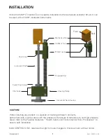
Turn Holdback Nut counter-clockwise until it reaches Mechanical Stop on Threaded Rod.
(See Inset.)
Spread open the Housing Clamp and place around the instrument Seal Housing with the
Threaded Rod aligned with the back of the instrument. (See Inset.)
Close the Housing Clamps and tighten the 7/16" bolts using a 5/8" wrench. The IT should now
be mounted on the instrument with the Threaded Rod parallel to the Instrument Shaft.
Slide the IT Shaft Lever up to Holdback Nut, and install the provided 1” Shaft Collar on the
instrument’s shaft Just below the Shaft Lever. The Shaft Collar should be installed with
screws facing towards the right side of the instrument’s enclosure when looking to enclosure
lid. The groove in the Shaft Lever should automatically fit over the Shaft Collar.
Turn the Holdback Nut clockwise until it comes into contact with the Shaft Lever.
Loosen the Socket Cap Screws on the instrument Seal Housing and open the ball valve.
Using a pipe wrench, turn the Holdback Nut clockwise until calculated insertion mark (see
individual product manual for directions) reaches the top of the Seal Housing.
Tighten Socket Cap Screws with a hex wrench.
Turn the Holdback Nut counter-clockwise until there is enough space to remove the IT Lever.
Loosen 7/16" bolts on the Housing Clamp and remove KAM IT Insertion Tool from Seal
Housing.
NOTE: If, during insertion, the Shaft Lever reaches the Housing Clamps prior to the insertion
mark reaching the top of the Seal Housing, repeat steps 2-9 in order to fully insert the
shaft to the calculated insertion depth.
CAUTION: Loosening Socket Cap Screws at any time without a properly installed Insertion Tool
or the shaft already fully retracted from the pipeline could cause the shaft assembly to forc-
ibly eject due to pressure in the pipeline, potentially causing bodily injury and/or damage to the
instrument.
INSTALLATION
1.
2.
3.
4.
5.
6.
7.
8.
9.
10.
11.
12.


