background image

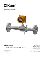
KAM

®

 LRW


LOW RANGE WATERCUT

TEL 

+1 713 784 0000  

FAX 

+1 713 784 0001  

Email

 Sales@Kam.com 

KAM CONTROLS, INC.


3939 Ann Arbor Drive 

Houston, Texas 77063 USA

www.KAM.com

User Manual

LRWMANUAL 0918

An ISO 9001 certified company

Summary of Contents for Simple Precision LRW

Page 1: ...LOW RANGE WATERCUT TEL 1 713 784 0000 FAX 1 713 784 0001 Email Sales Kam com KAM CONTROLS INC 3939 Ann Arbor Drive Houston Texas 77063 USA www KAM com User Manual LRWMANUAL 0918 An ISO 9001 certified...

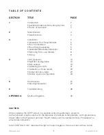
Page 2: ...guration 15 Data capture 19 Calibrating the LRW 21 Calibration with lab results 23 Output process values 24 Density input reconfiguration 24 5 Maintenance 27 Cleaning Inspection 27 6 Troubleshooting 2...

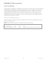
Page 3: ...pipelines with included static mixer and manual draw off valve LRW fixed insertion for pipelines 3 and up 2 3 or 4 flanged process connection LRW insertable retractable for pipelines 3 and up 2 3 or...

Page 4: ...e in density across the entire API gravity range Compensation is based on a density input from a mass flow meter or densitometer and all compensation is automatic This is paramount in situations where...

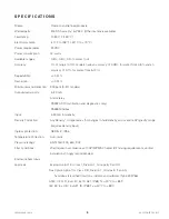
Page 5: ...y RS232 ASCII calibration and diagnostics only RS485 Modbus Input 4 20 mA for density Density Correction AnyDensity compensates for changes in fluid density across entire API gravity range requires de...

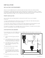
Page 6: ...the pipeline is heated that the heating trace be extended to include the LRW If the pipeline is not going to flow for extended amount of time and the pipe is not heated then LRW should be taken out to...

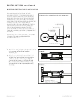
Page 7: ...opening ball valve is used to isolate the LRW sensor from the pipeline during installation or removal The seal housing of the LRW sensor allows the probe to be inserted and removed from the pipe under...

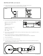
Page 8: ...Screws on the locking collar Push LRW sensor in until the mark is at the top edge of the locking collar Ensure that LRW flow indicator is aligned with pipeline flow direction FIG 3 7 5 MID 6 7 8 FIG 3...

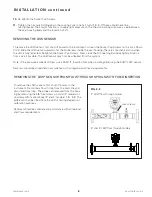
Page 9: ...Socket Cap Screws on the Lock Down Collar Slide the LRW sensor upward until the probe rests inside the seal housing There is a mechanical stop when the unit is fully retracted Retighten the Socket Ca...

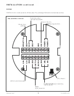
Page 10: ...CHS POWER POWER FIG 3 9 WIRING DIAGRAM 4 20 mA current loop output LCD connector Density input 4 20 mA Digital relay output open drain max 50 W Power input 12 24 V Chassis connection RS232 serial conn...

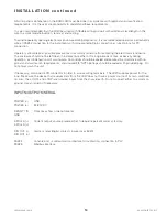
Page 11: ...ing diagnostics it is recommended operators permanently wire an RS232 connection to the instrument with corresponding 9 pin connection at junction box for PC connection Operators should take all possi...

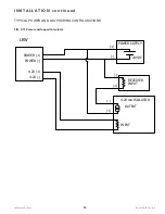
Page 12: ...ING THE 4 20 mA and power supply can not be the same or connected togeather 24VDC POWER SUPPLY POWER POWER 4 20 4 20 WRONG WIRING LRW PROVIDES POWER FOR THE 4 20mA loop adding external power can damag...

Page 13: ...12 RECEIVER INPUT POWER SUPPLY 24VDC POWER POWER 4 20 4 20 4 20 mA ISOLATOR INPUT OUTPUT WITH ISOLATOR LRW I N S TA L L AT I O N c o n t i n u e d TYPICAL POWER AND LOOP WIRING CONFIGURATIONS FIG 3 1...

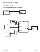
Page 14: ...NG DENSITY WIRING Density meter provides power for the 4 20mA output DENSITY IN GND LRW OUTPUT DESITY METER DESITY METER OUTPUT LRW DENSITY IN GND 2ND RECEIVER POWER SUPPLY OUTPUT 1 OUTPUT 2 POWER IN...

Page 15: ...SITY IN GND LRW POWER IN OUTPUT 2 POWER SUPPLY LRW DENSITY IN GND 4 20mA Signal Splitter 4 20mA Input OUTPUT 1 DENSITY WIRING Where density meter 4 20mA output requires external power DESITY METER OUT...

Page 16: ...IG 3 9 of this manual Connect the other end of RS232 cable to the serial port of your computer An RS232 cable for connecting your PC to the LRW has been supplied with the LRW as well as a USB adaptor...

Page 17: ...b FIG 4 2 and then configure setting to match below Baud 115200 Parity None Data Bits 8 Stop Bits 1 Hardware Flow Control 1 Port Select port number assigned to your serial port or USB port connected t...

Page 18: ...o n t i n u e d If not already turned on turn on power to LRW The initial greeting message will appear if the unit is newly powered up FIG 4 3 7 Click on the Send tab and select first four boxes under...

Page 19: ...capture function See next page 19 for instructions FIG 4 5 Column 1 percent water Column 2 minimum voltage V Column 3 maximum voltage V Column 4 minimum frequency Hz Column 5 frequency offset Hz Colu...

Page 20: ...ow will open If a folder is not already selected choose a folder and click open Name the data file and save to selected folder FIG 4 7 Click on Open Press the Start Overwrite button The screen will cl...

Page 21: ...R AT I O N c o n t i n u e d DATA CAPTURE IN REALTERM CONTINUED While capturing data the Capture window turns red FIG 4 8 Press Stop Capture to stop data capturing The saved file can be opened either...

Page 22: ...r content from the three samples Average the water content from the three LRW screen shots first data column Check the current reading of the LRW in RealTerm Subtract or add the value of the differenc...

Page 23: ...reading 0 11 high Current reading 3 0 To adjust the LRW the reading needs to be lowered by 0 11 3 0 0 11 2 89 This is the new value to be entered into the LRW K A M L R W O P E R AT I O N c o n t i n...

Page 24: ...a sample is drawn note or take a screen shot of the current LRW reading in the RealTerm window Send the samples to the lab for water content determination Once results have been received from the lab...

Page 25: ...s parameters will be displayed FIG 4 14 1 2 FIG 4 14 Density input values are configured at the factory according to information provided by the customer These values must match output values from the...

Page 26: ...end ASCII To change the values enter den4 4mA Density value and den20 20mA Density value and then click send ASCII For instance if the desired low end of the range was 0 8 g cm3 and the desired high e...

Page 27: ...nter api4 4mA Density value API and api20 20mA Density value API and click on Send ASCII For instance if the desired low end of the range was API 20 and the desired high end of the range was API 70 yo...

Page 28: ...cloth with oil solvent or part washer Preferred solvents include any petroleum solvent such as mineral spirits xylene toluene gasoline or diesel Do not use WD40 or other chemicals If you have a questi...

Page 29: ...d FIG 6 2 and set LCD display plate aside Remove the four 4 screws on the Terminal PCB with a Phillips screwdriver FIG 6 2 Carefully pull the Terminal Board away from the Processor board by firmly hol...

Page 30: ...is range check the field power supply and bring it within the limits above Check again If it is still not within limits contact KAM Controls for further assistance If the voltage across the input powe...

Page 31: ...W supplies power for the loop Make sure the device that receives data from the LRW does not have a power source of its own switched on Also the LOOP and LOOP are isolated inputs from the chassis earth...

Page 32: ...teps 1 through 4 on the previous section Loop Troubleshooting to access the terminal board of the LRW Check the RS232 wires connected to the LRW terminals for damage and ensure they are installed as p...

Page 33: ...RE HIGH ALARM BOOLEAN 3 TEMPERATURE LOW ALARM BOOLEAN 4 WATER CONTENT IN 32 BIT FLOAT 42000 RTD_TEMPERATURE 32 BIT FLOAT 42001 BOARD TEMPERATURE 32 BIT FLOAT 42002 API GRAVITY 32 BIT FLOAT 42003 DENSI...

Reviews: