


Summary of Contents for NUMITRON v5
Page 2: ...2 1 You have a PCB with ICs 2 Place all resistors vertical...
Page 3: ...3 3 Place photoresistor Make height of photoresistor equal buttons height...
Page 4: ...4 4 Place net resistors Common pin to square pad...
Page 5: ...5 5 Place all capacitors Be careful with polarity...
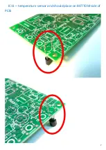
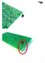
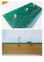
Page 7: ...7 IC11 temperature sensor and should place on BOTTOM side of PCB...
Page 8: ...8...
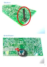
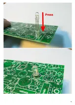
Page 9: ...9 7 Buttons 8 Install buzzer...
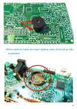
Page 10: ...10 9 Place battery holder and insert battery when clock will be fully assembled...
Page 12: ...12 12 Insert 6 RGB LEDs...
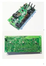
Page 13: ...13...
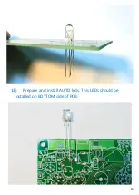
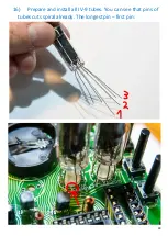
Page 14: ...14 13 Prepare and install AUTO leds This LEDs should be installed on BOTTOM side of PCB...
Page 15: ...15...
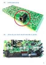
Page 16: ...16 14 Install power plug 15 After all your clock should looks like on photo...
Page 17: ...17...
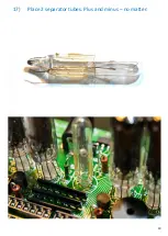
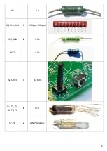
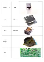
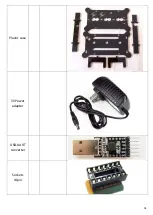
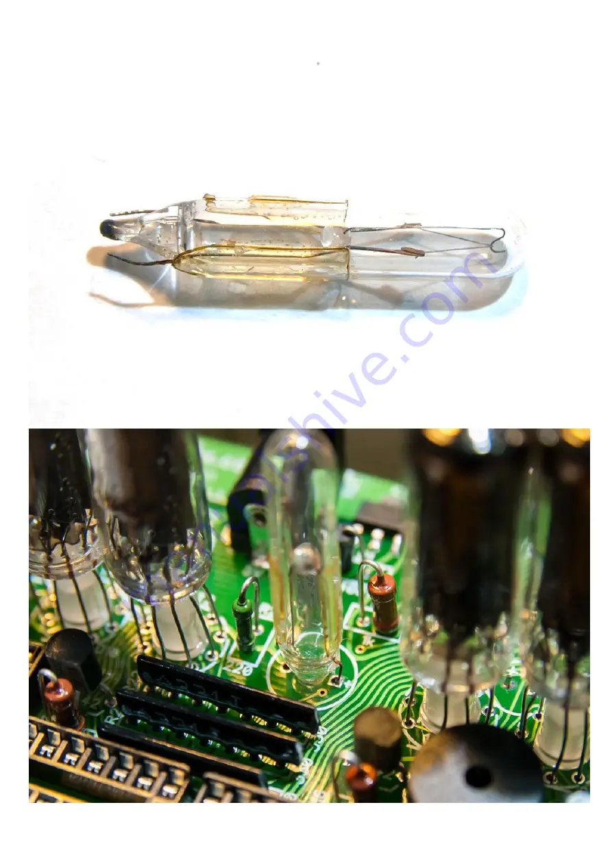
Page 19: ...19 17 Place 2 separator tubes Plus and minus no matter...
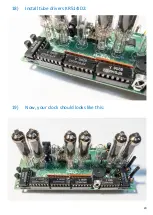
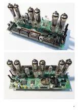
Page 20: ...20 18 Install tube drivers KR514ID2 19 Now your clock should looks like this...
Page 21: ...21...
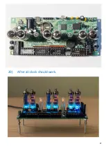
Page 22: ...22 20 After all clock should work...
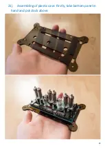
Page 23: ...23 21 Assembling of plastic case Firstly take bottom panel in hand and put clock above...
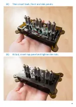
Page 24: ...24 22 Then insert back front and side panels 23 At last insert top panel and tighten the nuts...
Page 25: ...25 CONGRATULATIONS...
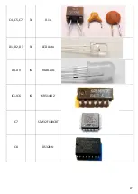
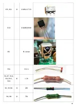
Page 30: ...30 VT1 VT7 7 A42 XS1 USB micro XS2 Power plug CR1220 battery holder PCB...
Page 31: ...31 Plastic case 5V Power adapter USB UART converter Sockets 14pin...
Page 32: ...32...


