


23
The Internal Back Plane
The back plane of the series 8000 rack system is typically hand wired at the factory. Channels
configured as blanks are normally left unconfigured because it is not always specified as to
what will be in a slot in the future. In designing the series 8000 modules some standards have
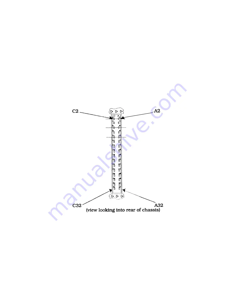
been adhered to accommodate expansion. The diagram in figure 12 details physical pin
locations for the standard Eurocard connector. Table 2 gives the electrical standards used for
designing compatible modules. Figure 15 is a template used for special wiring to the back
plane. See the section on
Adding Additional Modules
for information concerning expansion.
When connecting other 3rd party equipment to the Series 8000 you must take care to avoid
drawing to much power from the supply and/or adding additional noise to the output from the
system (especially with digital cards such as A/D, D/A, or CPU)
.
fig. 12 -- Physical Eurocard Pin Locations;
Summary of Contents for SERIES 8000
Page 2: ......
Page 9: ...9 fig 1 Full 19 Subrack Rear Front Outline Drawing...
Page 10: ...10 Fig 2 Full 19 Subrack Top View Outline Drawing...
Page 11: ...11 fig 3 Full 19 Subrack Rear Front with Display...
Page 12: ...12 fig 4 Full 19 Subrack Rear Front with Dual Display...
Page 14: ...14 fig 5 Rack with Display Outline Drawing...
Page 15: ...15 fig 6 Rack Outline Drawing...
Page 16: ...16 fig 7 Rack with Display Outline Drawing...
Page 28: ...28 fig 15 Back Plane Template...
Page 34: ...34 fig 20 Dual 1 8 DIN Mounting Panel 814873 002...


