40
3)
Pull off the switch cap and pop off the front of the meter panel using a small flat
head screwdriver and twisting slightly in the slot near the bottom center of the
panel.
Note:
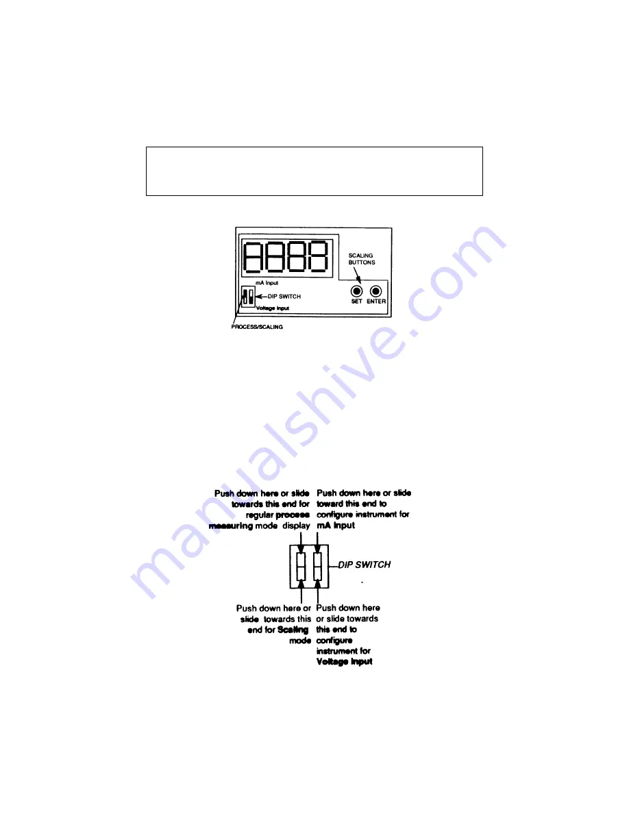
The DIP switch may either be a rocker type (press down on
appropriate end) or a slider type (slide toward appropriate
end). The drawing in fig. 26 details the adjustment
activities.
fig. 26 -- MCD 8000 Adjustment Switches;
4)
Actual calibration occurs in the SCALING mode. Push down or slide towards
the bottom the left most dip switch. This will put the unit in scaling mode and
the word "LO" will appear on the display.
fig. 27 -- Process/Scaling Dip Switch;
Summary of Contents for SERIES 8000
Page 2: ......
Page 9: ...9 fig 1 Full 19 Subrack Rear Front Outline Drawing...
Page 10: ...10 Fig 2 Full 19 Subrack Top View Outline Drawing...
Page 11: ...11 fig 3 Full 19 Subrack Rear Front with Display...
Page 12: ...12 fig 4 Full 19 Subrack Rear Front with Dual Display...
Page 14: ...14 fig 5 Rack with Display Outline Drawing...
Page 15: ...15 fig 6 Rack Outline Drawing...
Page 16: ...16 fig 7 Rack with Display Outline Drawing...
Page 28: ...28 fig 15 Back Plane Template...
Page 34: ...34 fig 20 Dual 1 8 DIN Mounting Panel 814873 002...


