background image

7

Timer 

1.96

with electronic room temperature control and room temperature sensor type 30076

Assembly and installation instructions

3. Installation

3.1 Fitting

The time switch should be mounted on a flat wall in a dry, dust-free room
with the controls on the front panel easily accessible. The housing is fixed
to the wall with three screws (the location of which is shown on the back
of the housing). As the sensor is a separate unit, the time switch can be
located in an adjacent room.

3.2 Installation of the room temperature sensor

As the sensor detects the room temperature at the point at which it is
located, it should be fixed in a place where the temperature measurement
will not be affected by its surroundings:
• approx. 1.5m above ground level on an internal wall. 
• away from doors and windows (draughts) 
• in front of curtains, blinds or furniture 
• out of direct sunlight 
• out of the direct airflow from heating units 
• away from other heat sources, such as heating units, lamps etc.
• Connection:

e.g. J-Y (ST) Y 4 x 2 x 0.8 mm; 

Cable length: max. 100 mm with 1.5 mm

²

3.3 Setting sensor should be located

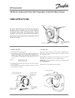
The switching differential can be set anywhere between 0.6K and 6K but
is pre-set with the smallest possible differential. If the heating system will
be frequently switched on and off, a higher differential can be set as 
follows:
• Switch off mains power and ensure that it cannot be switched on again.
• Remove temperature knobs on front of unit.
• Unscrew and remove front panel.
• Remove PCB carefully.
• Set switching differential on potentiometer P2 

Δ

• Reassemble unit.

Calibration

P2:
Switching
differential

Control PCB

Summary of Contents for 30076

Page 1: ...llation instructions Keep in a safe place for future reference Read carefully prior to commissioning 1 26 1 45 I 022 12 10 1 GB Timer 1 96 with electronic room temperature control and room temperature...

Page 2: ...to subsequent tradespersons and then to the end user or operator Retain this manual until the system is ultimately decommissioned 1 Important information 1 1 Correct and proper use 3 1 2 Safety inform...

Page 3: ...cuss your application with the manufacturer Any use other than the uses specified above is deemed not to be correct and proper The operator of the equipment alone shall be liable for any damage result...

Page 4: ...ociation of Electricians VDE regulations DIN and EN standards Attention Non compliance with these directives and the detailed instruction contained within this installation manual can cause the unit t...

Page 5: ...re control is used to control Kampmann heating units as a function of the room temperature The remote sensor detects the room temperature and should it be below the temperature pre set on the time swi...

Page 6: ...akes of switch is not recommended Any queries in this regard should be discussed with our technical staff Description Model 2 stage 3 phase switch 30051 3 stage 3 phase switch 30070 5 stage 3 phase co...

Page 7: ...its surroundings approx 1 5m above ground level on an internal wall away from doors and windows draughts in front of curtains blinds or furniture out of direct sunlight out of the direct airflow from...

Page 8: ...nsor is connected to the mains supply and so this work should only be carried out by a qualified electrician with responsibility for compliance with all safety guidelines To calibrate the sensor Deter...

Page 9: ...mode Setting the clock The time is set by turning the hour hand in a clockwise direction whilst ensuring that both the correct day and the correct time is set Day and time are critical as they are bot...

Page 10: ...mmand turn the Day Night selector in an anti clockwise direction I Heating mode Setback mode The manual command is automatically overridden at the next pin which reserves the switch command Manual ope...

Page 11: ...11 Timer 1 96 with electronic room temperature control and room temperature sensor type 30076 Assembly and installation instructions Notes...

Page 12: ......

Reviews: