KaCool D HC
Assembly, installation and operating instructions
13
5
Construction and function
5.1
Overview
14
13
12
11
10
9
8
7
6
5
4
3
2
1
15
15
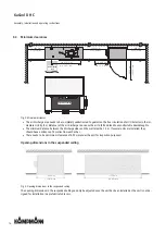
Fig. 1: KaCool D HC at a glance
1
Air vents
2
Water connections
3
Actuator
4
Electrical junction box
5
Heat exchanger
6
EC radial fan
7
Filter cassette epm1, 85 %
8
Condensate tray
9
Float switch
10
Condensate pump
11
Air baffle
12
Filter cassette epm1, 55 %
13
Inspection cover
14
Revision flap
15
Differential pressure bellows


