KaCool D HC
Assembly, installation and operating instructions
26
7
Electrical connection
IMPORTANT NOTE!
Condensation formation in the cooling unit!
In the event of on-site valve control, the cooling valve must be closed when the fans are switched off.
7.1
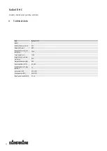
Maximum electrical rating values
KaCool D HC , electromechanical design (*00), F7/ F9 filter
Size
Nominal
voltage [V
AC]
Mains fre-
quency [Hz]
Nominal
power [W]
Nominal
current [A]
Leak-
age
current
[mA]
Ri ana-
logue in-
put [kΩ]
Max. fuse
[A]
IP class
Protection
class
1
230
50/60
100
0.8
0.21
100
B16A
IP20
I
Tab. 6: Maximum electrical connection values
7.2
Electromechanical control
7.2.1 Connection (*00)
Fig. 12: PCB in the electrical junction box
Power supply and control:
The unit needs a 230 V / 50 Hz power supply. The fan speed
of the EC fan installed can be continuously variably controlled
via the 0-10 V DC (Ri = 100 kOhm) control input. The internal
motor electronics detects any possible motor malfunction and
automatically switches off the fan.
The electrical junction box accommodate potential free con-
tacts max. 250 V / 2 A to evaluate the filter message (NO)
and the condensate alarm (NC). The contact C-P1, P2 is open
and the contact C-AP is closed in fault-free normal operation.
Alternatively, the condensate alarm can also be evaluated as
a switched 230 V signal via terminal ‘cp’. Terminal ‘cp’ carries
230 V AC voltage in fault-free normal operation.

